

Smoke exhaust barrel with jet technology for hot-blast stove
A jet technology, hot blast stove technology, applied in the directions of induced draft, lighting and heating equipment, combustion method, etc., can solve the problems affecting the normal operation of the boiler, damage, the failure of the induced draft fan, etc., to achieve good smoke exhaust effect, convenient maintenance, The effect of low failure rate
Inactive Publication Date: 2013-12-18
孙长杰
View PDF13 Cites 2 Cited by
- Summary
- Abstract
- Description
- Claims
- Application Information
AI Technical Summary
Problems solved by technology
[0002] The smoke exhaust fan of the existing stove is generally installed in the chimney, because the fan works at a high temperature, the fan often breaks down, or even damages, directly affecting the normal operation of the boiler
Method used
View moreImage
Smart ImageViewing Examples

Examples
Embodiment Construction
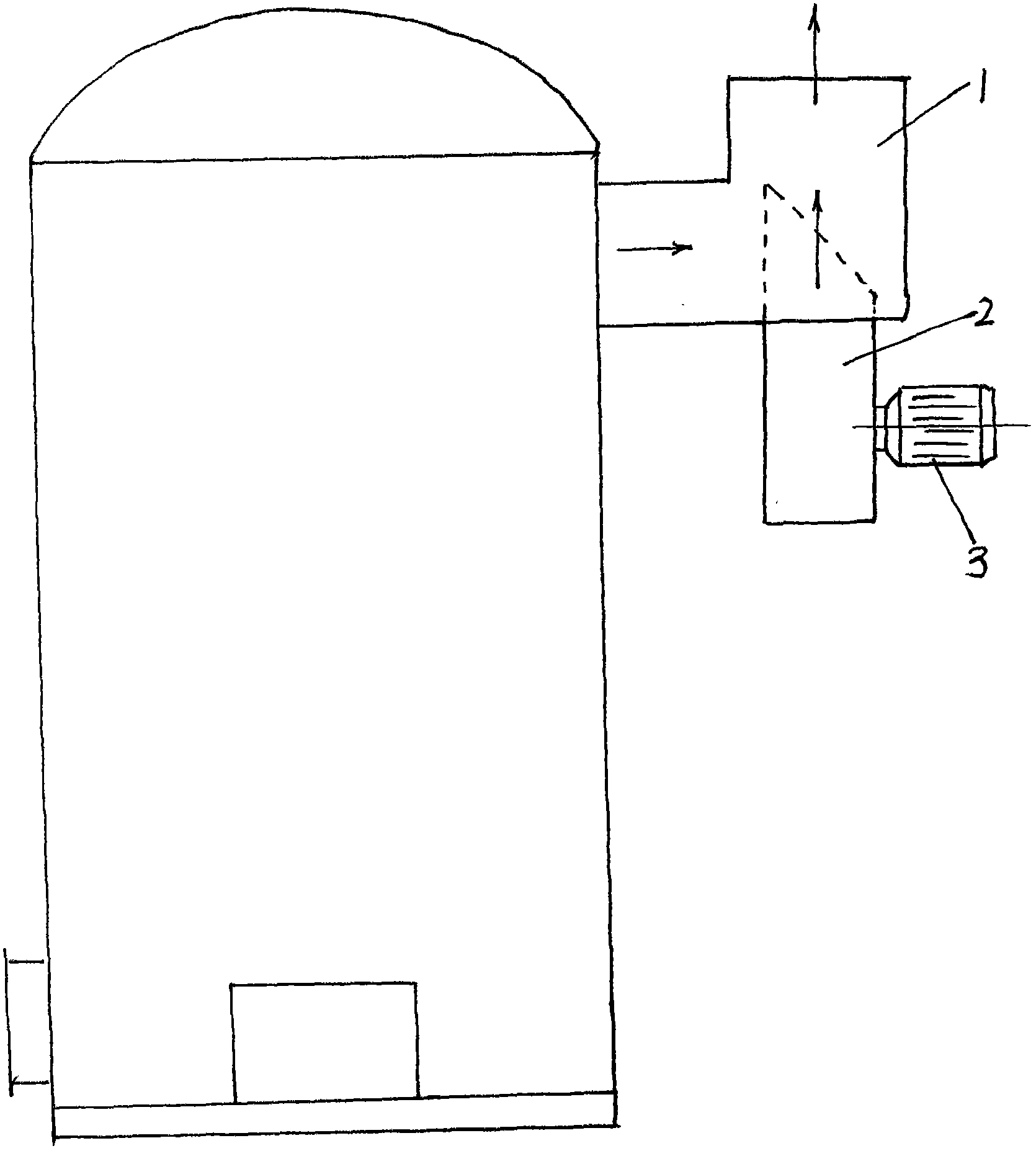
[0009] A chimney for a hot blast stove with jet technology, comprising a chimney 1, an air inlet is provided at the bottom of the chimney 1, an air inlet pipe 2 is inserted into the air inlet, and the upper part of the air inlet pipe 2 penetrates into the chimney 1, and the air inlet The lower part of the pipe 2 is arranged outside the chimney 1, and the lower part of the air inlet pipe 2 located outside the chimney 1 is equipped with a smoke exhaust fan 3, and the air outlet of the smoke exhaust fan 3 is connected and communicated with the lower port of the air inlet pipe 2, The upper end of the air inlet pipe has a groove at an angle of 45 degrees.
Login to View More PUM
 Abstract
The invention discloses a smoke exhaust barrel with a jet technology for a hot-blast stove. The smoke exhaust barrel comprises a smoke barrel. An air inlet is formed in the bottom of the smoke barrel, an air inlet tube penetrates the inside of the air inlet, the upper portion of the air inlet tube penetrates the inside of the smoke barrel, the lower portion of the air inlet tube is arranged on the outside of the smoke barrel, a smoke exhaust fan is arranged on the lower portion, which is positioned on the outside of the smoke barrel, of the air inlet tube, and an air outlet of the smoke exhaust fan is connected and communicated with a lower port of the air inlet tube. Compared with the prior art, the smoke exhaust barrel has the advantages of simple structure, convenience in maintenance, low failure rate, good smoke exhaust effect and the like. Besides, shortcomings of high cost, maintenance rate and damage rate of an existing smoke exhaust induced draft fan when the existing smoke exhaust induced draft fan works in a high-temperature state are overcome.
Description
technical field [0001] The invention relates to a stove, in particular to a hot blast stove chimney with jet technology. Background technique [0002] The smoke exhaust fan of the existing stove is generally installed in the chimney. Since the fan works at a high temperature, the fan often breaks down or even gets damaged, which directly affects the normal operation of the boiler. Contents of the invention [0003] The purpose of the present invention is to solve the defects and deficiencies of the above-mentioned prior art, and to provide a hot blast stove chimney with jet technology [0004] The technical solutions adopted are: [0005] A chimney for a hot blast stove with jet technology, comprising a chimney, characterized in that the bottom of the chimney is provided with an air inlet, and an air inlet pipe is inserted into the air inlet, and the upper part of the air inlet pipe is inserted into the chimney Inside, the lower part of the air inlet pipe is arranged out...
Claims
Login to View More Application Information
Patent Timeline
 IPC IPC(8): F23L17/02
Inventor孙长杰
Owner孙长杰