Glue machine

A technology of glue brushing machine and frame, applied in the direction of coating, the device for coating liquid on the surface, etc., can solve the problems of unsatisfactory glue brushing effect, potential safety hazards, single mechanical structure of glue brushing machine, etc., to achieve the effect of gluing Ideal, highly automated, eliminates adverse effects

A technology of glue brushing machine and frame, applied in the direction of coating, the device for coating liquid on the surface, etc., can solve the problems of unsatisfactory glue brushing effect, potential safety hazards, single mechanical structure of glue brushing machine, etc., to achieve the effect of gluing Ideal, highly automated, eliminates adverse effects

CN103464331BInactive Publication Date: 2017-06-13JIANGSU ZHENGDELI MECHANICAL TECH

Image

  • Glue machine
  • Glue machine

Examples


Embodiment Construction

[0019] In order to deepen the understanding of the present invention, the present invention will be further described below in conjunction with the embodiments and accompanying drawings. The embodiments are only used to explain the present invention and do not constitute a limitation to the protection scope of the present invention.

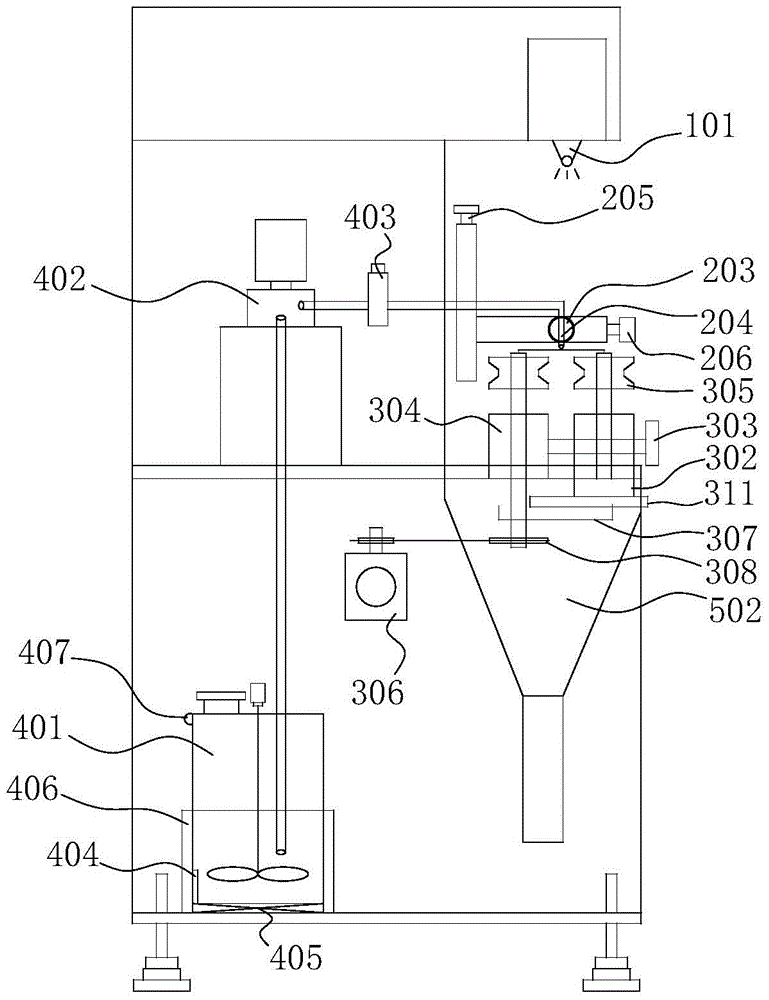
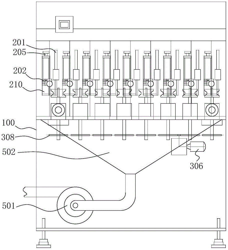
[0020] see figure 1 and figure 2 As shown, a glue brushing machine includes a frame 100, a two-dimensional guide rail device, a conveying device, a glue supply system, and an air suction system, wherein,

[0021] The top of the frame 100 is provided with a two-dimensional guide rail device, and the two-dimensional guide rail device includes several regularly arranged rubber head racks 210, and any one of the rubber head racks 210 includes a support rod 201, a needle holder 202, and an indexing plate 203 , the needle 204, the support rod 201 is movably connected with the frame 100 through the Z-direction bolt 205, and the Y-direction stroke of t...


PUM


Abstract

The invention discloses a glue brushing machine, which comprises a frame. A two-dimensional guide rail device is arranged on the top of the frame. There is a conveying device for conveying the workpieces to be glued. The glue supply system transports the glue in the glue storage tank to the needles on each glue head rack through the connecting pipe through the connecting pipe. The system is used to suck out the toxic gas released by the glue during the glue brushing process and treat it in a unified manner, so as to ensure the safety of workers' work. The glue brushing machine described in the present invention has high automation, high glue brushing efficiency, ideal glue application effect and stable performance. it is good.

Description

technical field [0001] The invention relates to a gluing device, in particular to a gluing machine used for flocking on the outer edge of an automobile window. Background technique [0002] As an important supporting equipment in the automatic assembly line for flocking flocking on the outer edge of the car window, the flocking glue brushing machine is mainly used for the glue brushing process before the flocking on the outer edge of the car window. The surface to be flocked along the strip is covered with a rubber surface of uniform thickness to ensure the smooth progress of the subsequent flocking process. [0003] The flocking machine in the general factory workshop is not highly automated during the working process, requiring a large number of staff to manually operate, which cannot meet the requirements of the ever-changing product structure. When the structure changes, especially when the glue brushing position changes, its control ability is not strong, and the struc...

Claims


Application Information

Patent Timeline
13 Jun 2017
Publication
CN103464331B
IPC
B05C1/06; B05C11/10
Inventors
郑士垟