Welding device and control method thereof

A welding device and welding condition technology, which is applied in welding equipment, manufacturing tools, arc welding equipment, etc., can solve the problems that the arc striking effect cannot meet expectations, the design difficulty is increased, and the dynamic response performance is not high, so as to achieve excellent arc striking and Welding effect, the effect of shortening the control cycle

Active Publication Date: 2013-12-25
PANASONIC WELDING SYST TANGSHAN
View PDF6 Cites 6 Cited by
  • Summary
  • Abstract
  • Description
  • Claims
  • Application Information

AI Technical Summary

Problems solved by technology

However, because the difference between the output energy and the target energy at this time is relatively large, if the dynamic response performance of the control system is not high, the control cycle for adjusting the arc ignition energy wil

Method used


Image

  • Welding device and control method thereof
  • Welding device and control method thereof
  • Welding device and control method thereof

Examples


Embodiment Construction
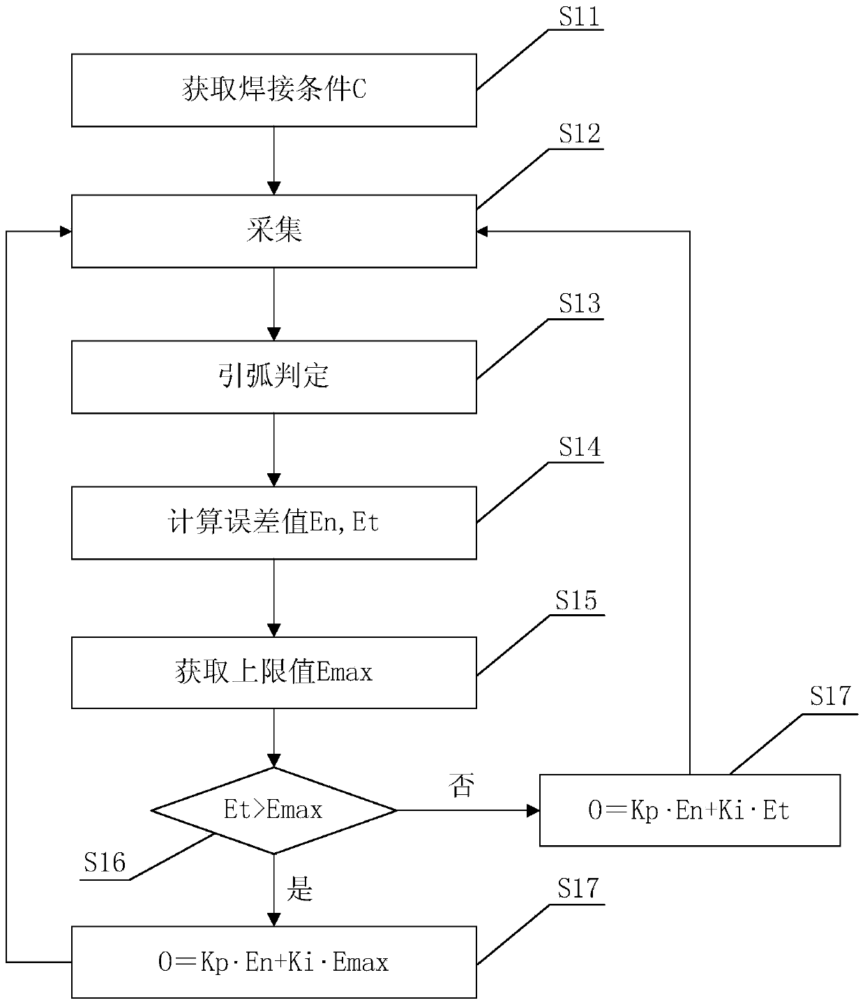
[0023] The core idea of ​​the present invention is to pre-set the upper limit value Emax and the corresponding relationship R of the welding condition C and the arc striking stage f, then obtain the welding condition C, determine the arc striking stage f, and then according to the corresponding relationship R, welding condition C and In the arc ignition stage f, a reasonable and specific upper limit value Emax is obtained. Then, according to the reasonable upper limit Emax, a reasonable opening value O is obtained, so as to reasonably control the output energy of the welding machine.

[0024] Specific embodiments of the present invention will be described below in conjunction with the accompanying drawings.

[0025] [welding device]

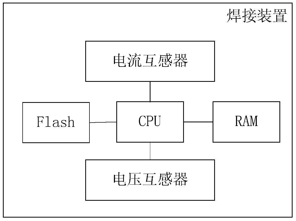
[0026] Refer below figure 1 with figure 2 The welding device of the present invention is described.

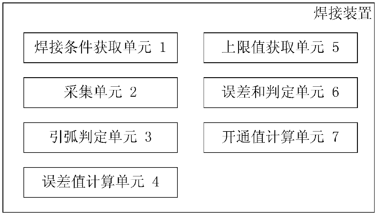
[0027] Such as figure 1 As shown, the welding device of the present invention includes: a welding condition acquisition unit 1, an acqui...


PUM


Abstract

The invention provides a welding device and a control method thereof and belongs to the field of welding technology. The welding device comprises a welding condition acquisition unit, a collection unit, an arc strike determination unit, an error calculation unit, an upper limit acquisition unit, and an on value calculation unit. The welding condition acquisition unit is used for acquiring predetermined welding conditions. The collection unit is used for collecting welding current. The arc strike determination unit is used for determining an arc strike phase according to the welding current. The error calculation unit is used for calculating errors of current state and sum of integral accumulative errors according to the welding current. The upper limit acquisition unit is used for acquiring a specific upper limit according to an upper limit of the predetermined integral accumulative error sum, correspondence between the welding conditions and the arc strike phase, the welding conditions, and the arc strike phase. The on value calculation unit is used for calculating an on value of a power device according to determination results of an error sum determination unit. The welding device and the control method thereof have the advantage that arc striking and welding can be well effective.

Description

[technical field] [0001] The invention relates to the field of welding technology, in particular to a welding device and a control method thereof. [Background technique] [0002] People have been exploring and researching arc ignition and welding technology of electric welding machines, with the aim of achieving excellent arc ignition and welding effects, and improving welding quality and welding efficiency. The arc ignition process is divided into two main stages: the first stage is the early stage of arc ignition. In the later stage, in this stage, the arc is gradually ignited, the no-load voltage gradually changes to the arc voltage, and the welding current is output to enter the welding process. [0003] In order to obtain an excellent arc striking effect, it is necessary to continuously adjust the output energy of the welding machine during the arc striking process. Usually, the method of adjusting the output energy of the welding machine is to adjust the opening valu...

Claims


Application Information

Patent Timeline
IPC IPC(8): B23K9/00B23K9/06B23K9/095
Inventor 李文举王帅韩勇赵素梅李松惠昭
Owner PANASONIC WELDING SYST TANGSHAN
Why Eureka
Try Eureka