Middle trough welding system

A welding system and welding machine technology, applied in welding equipment, welding equipment, auxiliary welding equipment, etc., can solve the problems that the welding process in the middle groove cannot realize automatic operation, so as to improve welding efficiency and quality, improve the accuracy of clamping, The effect of precise clamping and fixing

Active Publication Date: 2013-12-25
斯图加特航空自动化(青岛)有限公司
View PDF4 Cites 12 Cited by
  • Summary
  • Abstract
  • Description
  • Claims
  • Application Information

AI Technical Summary

Problems solved by technology

[0004] The middle groove welding system provided by the present invention solves the problem that the existing middle groove welding process cannot realize automatic operation

Method used


Image

  • Middle trough welding system
  • Middle trough welding system
  • Middle trough welding system

Examples


Embodiment Construction

[0024] In order to make the object, technical solution and advantages of the present invention clearer, the implementation manner of the present invention will be further described in detail below in conjunction with the accompanying drawings.

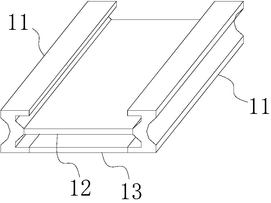
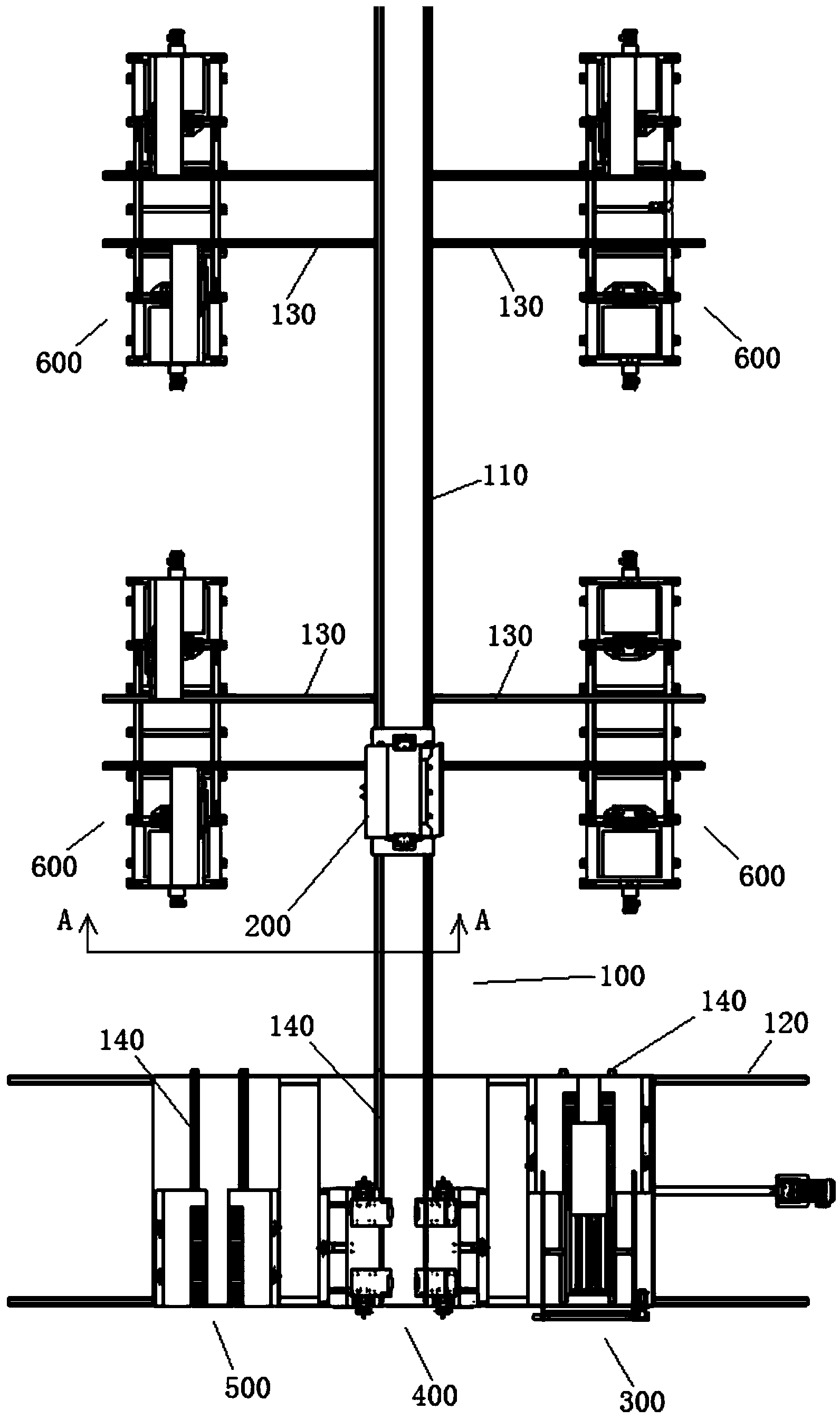
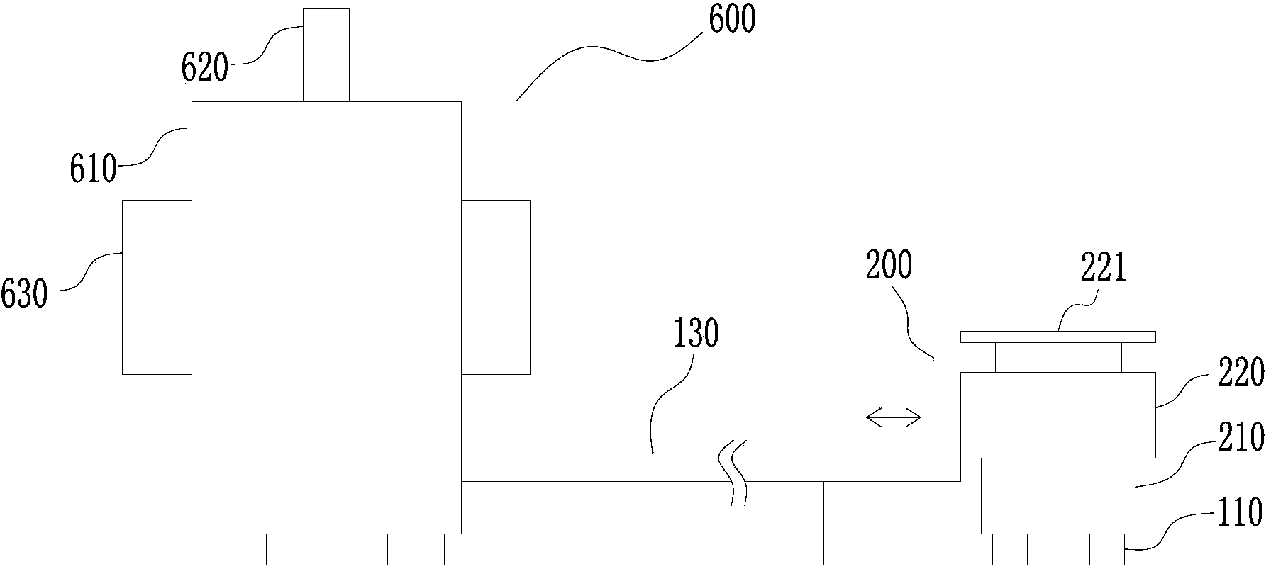
[0025] see figure 2 , a middle groove welding system, the system includes a track network 100, a mother and child transport vehicle 200, a bottom feeder 300 for conveying the bottom plate, a middle plate feeder 400 for conveying the middle plate and channel steel, and a Output the middle tank unloading machine 500 of the middle tank and a plurality of middle tank welding machines 600 for welding the bottom plate, the middle plate and the channel steel into the middle tank. The bottom plate feeder 300, the middle plate feeder 400 and the middle trough feeder 500 are respectively located at different positions of the track network 100; 100, for sending the parts to be welded of the bottom plate feeder 300 and the middle plate feeder 40...


PUM


Abstract

The invention discloses a middle trough welding system. The system comprises a rail net, primary and secondary transport vehicles, a bottom plate feeding machine for transporting bottom plates, a medium plate feeding machine for transporting medium plates and steel channels, a middle trough blanking machine for outputting middle troughs, and a plurality of middle trough welding machines for welding the bottom plates, the medium plates and the steel channels into the middle troughs, wherein the bottom plate feeding machine, the medium plate feeding machine and the middle trough blanking machine are respectively positioned at different positions of the rail net; the primary and secondary transport vehicles run on the rail net for transporting the bottom plates and the medium plates and the steel channels of the bottom plate feeding machine and the medium plate feeding machine to the corresponding middle trough welding machines, and transporting the middle troughs welded by the middle trough welding machine to the middle trough blanking machine. On the basis of guaranteeing the welding quality, the automatic and batch operation of welding the middle troughs is realized.

Description

technical field [0001] The invention relates to a middle groove welding process, in particular to an automatic middle groove welding system. Background technique [0002] The middle trough is the fuselage and material carrying mechanism of the scraper conveyor, and its performance directly affects the reliability and service life of the scraper conveyor. Such as figure 1 As shown, the middle channel mainly includes channel steel 11 on both sides and a middle plate 12 and a bottom plate 13 welded between the two channel steels. At present, the welding of the middle groove is mainly done manually. First, the middle plate 12 points are fixed between the two channel steels 11, and then the workpiece is turned over by means of a crane, and the welding operation is carried out manually with a welding torch. After the middle plate is welded, through the same The mode base plate 13 is welded between two channel steels. The above-mentioned traditional middle groove welding process...

Claims


Application Information

Patent Timeline
Patent Type & Authority Applications(China)
IPC IPC(8): B23K31/02B23K37/00
Inventor 肖宁肖林
Owner 斯图加特航空自动化(青岛)有限公司
Why Eureka
Try Eureka