
Sliding rail lifting device

A technology of lifting device and slide rail, which is applied in the direction of lifting device, lifting frame, metal processing, etc., to achieve the effects of easy installation and debugging, reducing slide rail damage, and saving floor space

Inactive Publication Date: 2013-12-25
INST OF OPTICS & ELECTRONICS - CHINESE ACAD OF SCI
View PDF6 Cites 8 Cited by
  • Summary
  • Abstract
  • Description
  • Claims
  • Application Information

AI Technical Summary

Problems solved by technology

[0004] The purpose of the present invention is to solve the existing technical problems, to provide a lifting device with good stability during transportation and without manpower

Method used


Image

  • Sliding rail lifting device
  • Sliding rail lifting device
  • Sliding rail lifting device

Examples


Embodiment Construction

[0031] In order to make the object, technical solution and advantages of the present invention clearer, the present invention will be described in further detail below in conjunction with specific embodiments and with reference to the accompanying drawings.

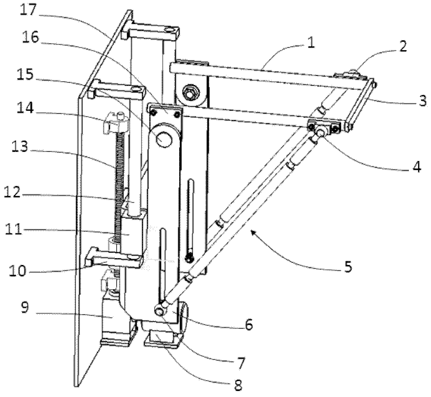
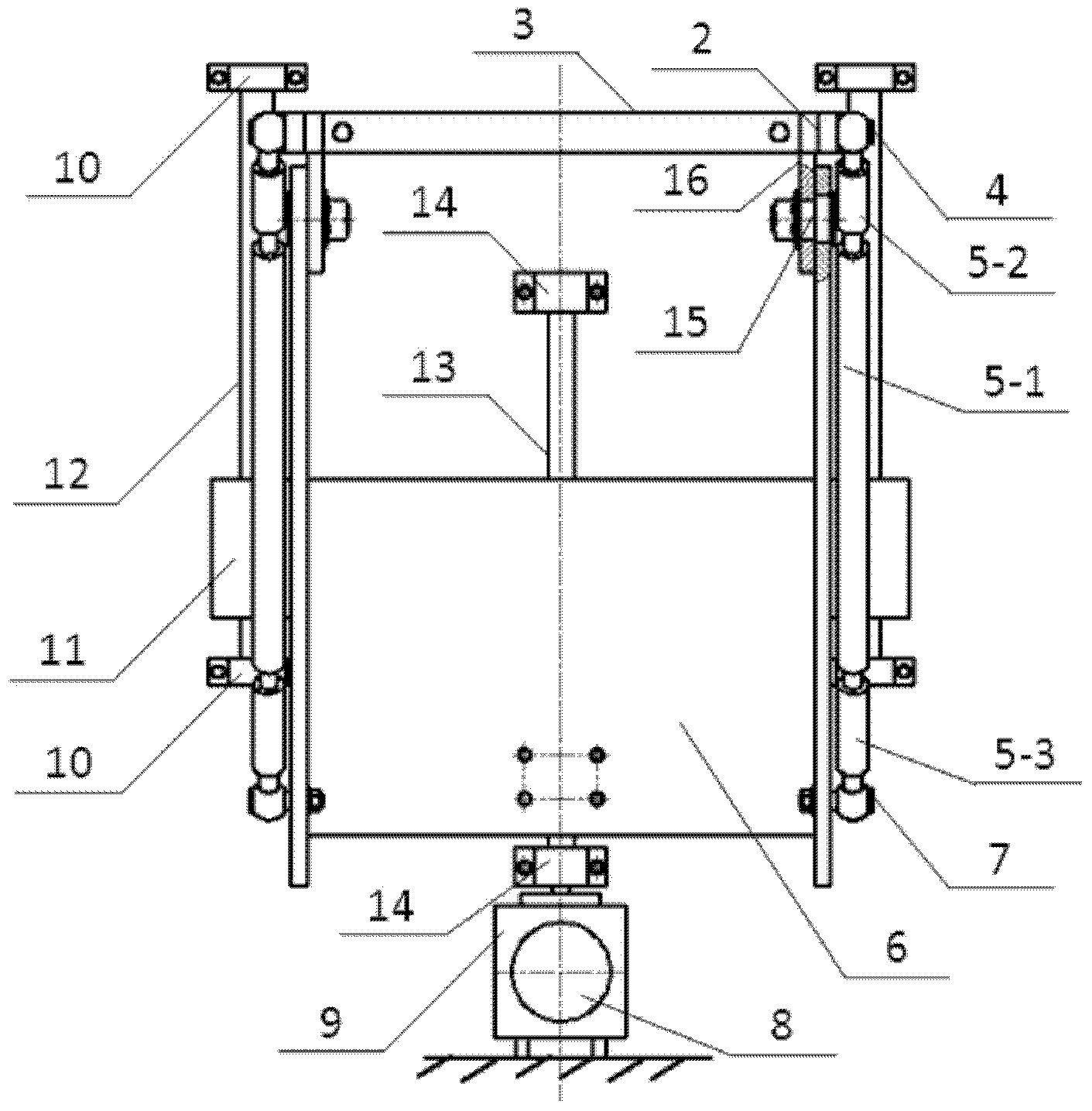
[0032] refer to Figure 2-Figure 6 The slide rail lifting device includes two slide rails 1, two connecting blocks 2, a connecting plate 3, two connecting shafts 4, two adjusting rods 5, a bracket 6, two supporting shafts 7, two rotating shafts 15 and The lifting parts composed of two support plates 16, two sets of sliding parts composed of guide rod supports 10, bearings 11 and guide rods 12, and the driving mechanism composed of motor 8, reducer 9, screw 13 and support 14, As well as the base plate 17 perpendicular to the horizontal plane, the lifting component is driven by the driving component to perform lifting movement under the cooperation of the sliding component.

[0033] In the lifting part, the two slide rails...


PUM


Abstract

The invention discloses a sliding rail lifting device. The sliding rail lifting device comprises a lifting component, two groups of sliding components, a driving component and a substrate, wherein the lifting component is formed by two mutually-parallel sliding rails, two connecting blocks, a connecting plate, two connecting shafts, two adjusting rods, a support, two supporting shafts, two rotating shafts and two supporting plates; the two groups of the sliding components are formed by guide rods, guide rod supports and bearings; the driving component is formed by a motor, a speed reducer, a screw rod and a screw rod support; the parallelled sliding rails in the lifting component are arranged on the support through the adjusting rods and the supporting plates; the guide rods of the two groups of the sliding components are parallel to each other, are vertical to the horizontal surface and are fixedly arranged on the substrate, and the bearings are fixedly connected with the support in the lifting component; a screw rod nut in the driving component is fixedly connected with the support in the lifting component; the lifting component is driven to do lifting motion by the driving component under the guide of the sliding components. The sliding rail lifting device disclosed by the invention has the advantages that a connection action of the sliding rails is omitted, human power is not needed, and a connection process is smoother; installation and adjustment are convenient due to the horizontal adjustment of the sliding rails, and the damage to the sliding rails and the occupied space are reduced.

Description

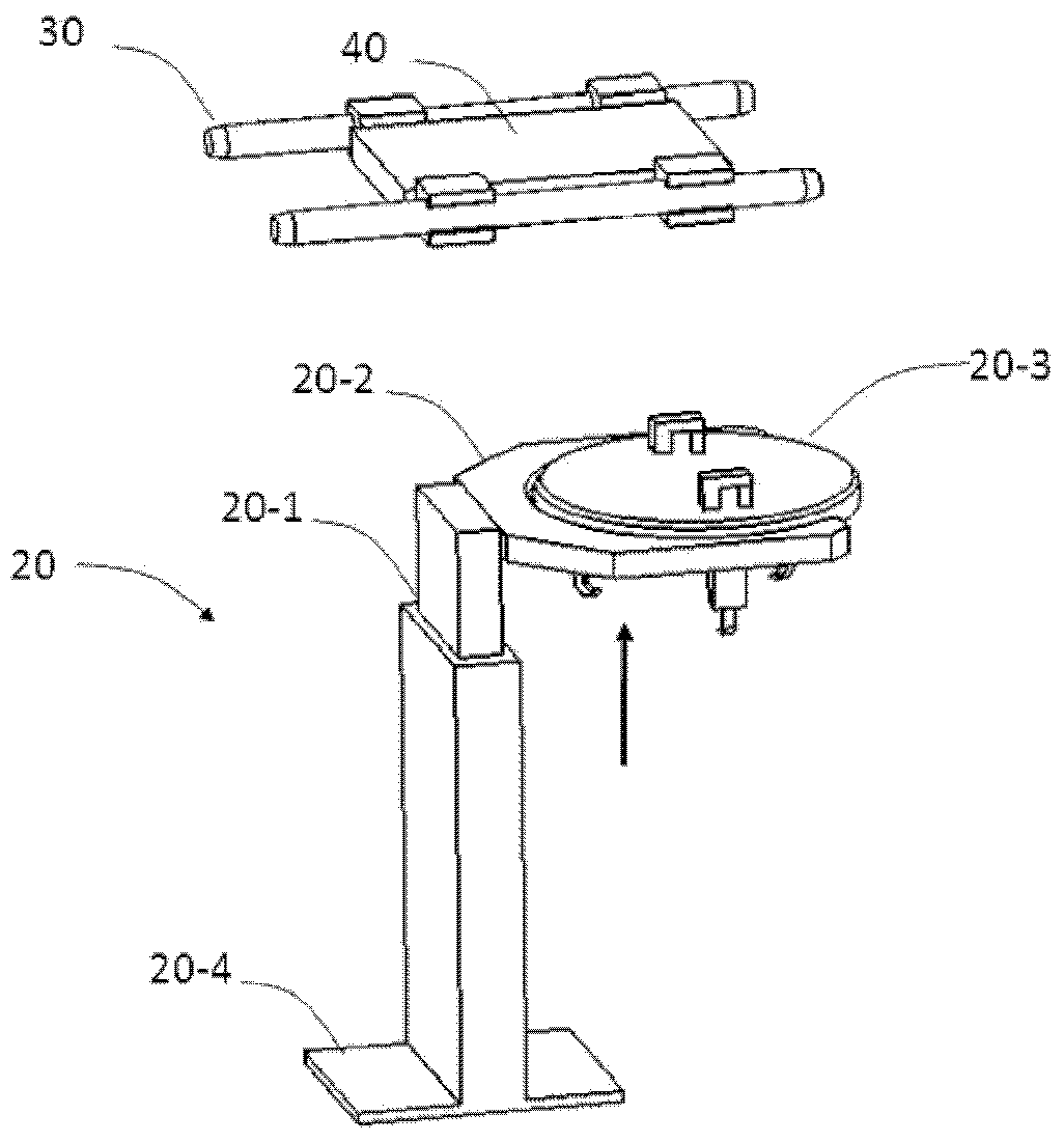
technical field [0001] The invention relates to a lifting device, in particular to a lifting device for conveying workpieces through sliding rails in machining equipment. Background technique [0002] In some large-scale mechanical equipment that processes a single part, due to its own characteristics (shape, volume, quality) and processing accuracy requirements, the workpiece to be clamped is transported to the processing position through the sliding track The method of uploading to ensure its stability during the transmission process. For example, in the ion beam correction equipment for precision optical device processing, the workpiece is conveyed by slide rails. Since the slide rail in the equipment has a certain height, a lifting device is required to send the workpiece from the clamping position to the slide rail, and the accuracy of the workpiece clamping must be maintained during the transportation process. [0003] Such as figure 1 Shown is a schematic diagram o...

Claims


Application Information

Patent Timeline
IPC IPC(8): B23Q7/00B66F7/22
Inventor 付韬韬王安定
Owner INST OF OPTICS & ELECTRONICS - CHINESE ACAD OF SCI
Learn More