Fully automatic binding machine

A binding machine, fully automatic technology, applied in binding and other directions, can solve the problems of high cost, difficult processing, heavy rotary wheel, etc., and achieve the effect of simple structure, stable operation and high reliability

Active Publication Date: 2013-12-25
曹东华
View PDF11 Cites 21 Cited by
  • Summary
  • Abstract
  • Description
  • Claims
  • Application Information

AI Technical Summary

Problems solved by technology

The rotary wheel is very heavy, difficult to process, and high in cost. In order to solve this technical problem, a Chinese invention patent with the Chinese invention patent No. Solution, it needs to use a motor to drive the rotary shaft, and use another motor to drive the heating assembly to rise and fall. Although the structure of the rotary wheel is cancelled, it does not simplify the structure of the binding machine, nor does it reduce the use of motors , very limited in terms of cost reduction and control

Method used


Image

  • Fully automatic binding machine
  • Fully automatic binding machine
  • Fully automatic binding machine

Examples


Embodiment Construction

[0025] The following descriptions are only preferred embodiments of the present invention, and therefore do not limit the protection scope of the present invention.

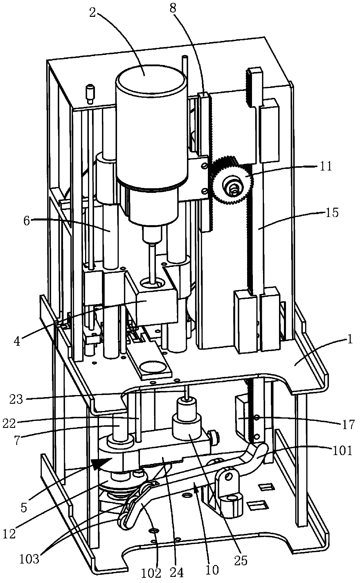
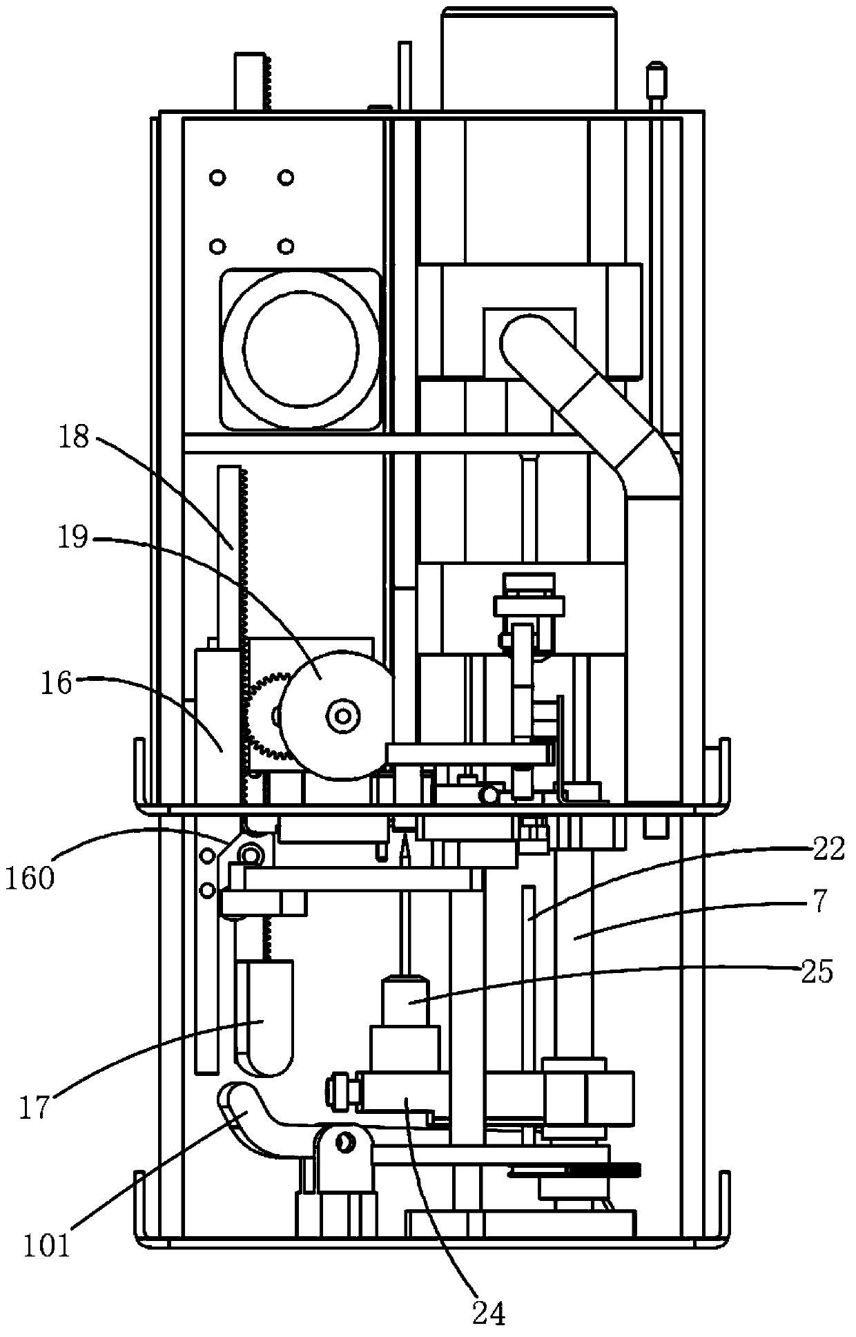
[0026] Examples, see Figure 1 to Figure 7 Shown: a fully automatic binding machine, including a frame 1, a drilling motor 2, a motor 3, an upper pressure head 4 and a lower heating assembly 5, the frame 1 is provided with several guide columns 6, and the frame 1 is provided with a rotary shaft 7. One end of the lower heating assembly 5 is slidably sleeved on the rotary shaft 7 , and a thimble 23 is provided on the top of the lower heating assembly 5 .

[0027] The drilling motor 2 and the upper pressing head 4 are slidably sleeved on the guide column 6, and the motor 3 is connected to a drilling rack 8 for driving the drilling motor 2 up and down. The drilling rack 8 is fixed on the drilling motor 2, and the motor 3 is also connected with a driving rack group for driving the lower heating assembly 5 to rotate a...


PUM


Abstract

The invention discloses a fully automatic binding machine. A motor is connected with a drilling rack and a driving rack set for driving a lower heating component to rotate and lift; a rotating shaft is connected with the driving rack set through a steel wire and a transmission mechanism; a rack is pivotally connected with a lever; a first end of the lever extends to the space below the driving rack set, and a second end of the lever extends to the space below the rotated lower heating component; after the lower heating component is rotated to a pressing rivet position, the driving rack set is butted against the first end of the lever in a descending process of the driving rack set, so that the lower heating component is lifted up to a heating riveting position by the second end of the lever. A drilling tool is driven by the drilling motor to drill in a rotary mode; a rotary function of the lower heating component, a lifting function of the lower heating component, a rubber pipe delivery function and a pipe cutting function are simultaneously realized by using the motor; the fully automatic binding machine has the advantages of simple structure, low cost, stable action and higher reliability.

Description

technical field [0001] The invention relates to the technical field of binding machines, in particular to an automatic binding machine. Background technique [0002] In the prior art, a fully automatic financial binding machine that realizes fully automatic punching, feeding, cutting and riveting, such as the Chinese invention patent application number "200610150287.1", the patent name "Multifunctional Automatic Binding Machine" and the Chinese The invention patent application number is "201210275624.5", and the patent name is "a rotary pipe delivery mechanism and a binding machine equipped with the mechanism". The Chinese invention patent number is "201220383975.3", and the patent name is "an automatic As shown in the Chinese invention patent of "Binding Machine", it includes a rotary shaft, a lower heating assembly and a rotary wheel. A thimble protrudes from the top of the lower heating assembly to set the rubber hose. The rotary shaft needs to be driven by a motor for T...

Claims


Application Information

Patent Timeline
Patent Type & Authority Applications(China)
IPC IPC(8): B42B5/02B42B5/08B42B5/00
Inventor 曹东华
Owner 曹东华
Why Eureka
Try Eureka