
Air source plasma pyrography device and painting method thereof
A plasma and plasma torch technology, which is applied to the field of air source plasma pyrography and painting, can solve the problems of low work efficiency, increased use cost, complicated device, etc., and achieves reduced use cost, portability, and volume. small effect
- Summary
- Abstract
- Description
- Claims
- Application Information
AI Technical Summary
Problems solved by technology
Method used
Image

Examples
Embodiment Construction
[0017] The present invention will be further explained below in conjunction with the specific implementation of examples.
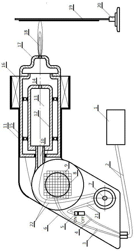
[0018] An air source plasma torch pyrography device includes a plasma generator and a plasma power source 1 .
[0019] The plasma generator includes a working handle 6 and an outer electrode 11 and an inner electrode 12 arranged above the working handle 6 . An inner electrode moving track 15 is provided between the inner electrode 12 and the outer electrode 11, and the inner electrode 12 is arranged in the outer electrode 11 through the inner electrode moving track 15. A gas chamber 13 is formed in the inner electrode 12, and one end of the inner electrode 12 and the outer electrode correspond to each other. A compressed air outlet 14 is provided.
[0020] A nozzle 17 is provided on one side of the outer electrode.
[0021] The working handle 6 is provided with a plasma intensity controller 7, a plasma connection switch 5 and a fan. The plasma intensit...
PUM
 Abstract
Description
Claims
Application Information