Pressurization control loop and method of piling machinery power head

A technology of pile machinery and control circuit, which is applied in the field of pressurization control circuit of pile machinery power head, which can solve the inconvenient operation of pressurized hoisting/releasing rope, uncontrollable pressure of power head, and lifting/lowering speed Mismatch etc.

Active Publication Date: 2013-12-25
SUNWARD INTELLIGENT EQUIP CO LTD
View PDF6 Cites 15 Cited by
  • Summary
  • Abstract
  • Description
  • Claims
  • Application Information

AI Technical Summary

Problems solved by technology

[0004] The present invention provides a pressurization control circuit and method for the power head of a piling mac

Method used


Image

  • Pressurization control loop and method of piling machinery power head
  • Pressurization control loop and method of piling machinery power head

Examples


Embodiment Construction

[0048] The present invention will be further described below in conjunction with the accompanying drawings and embodiments.

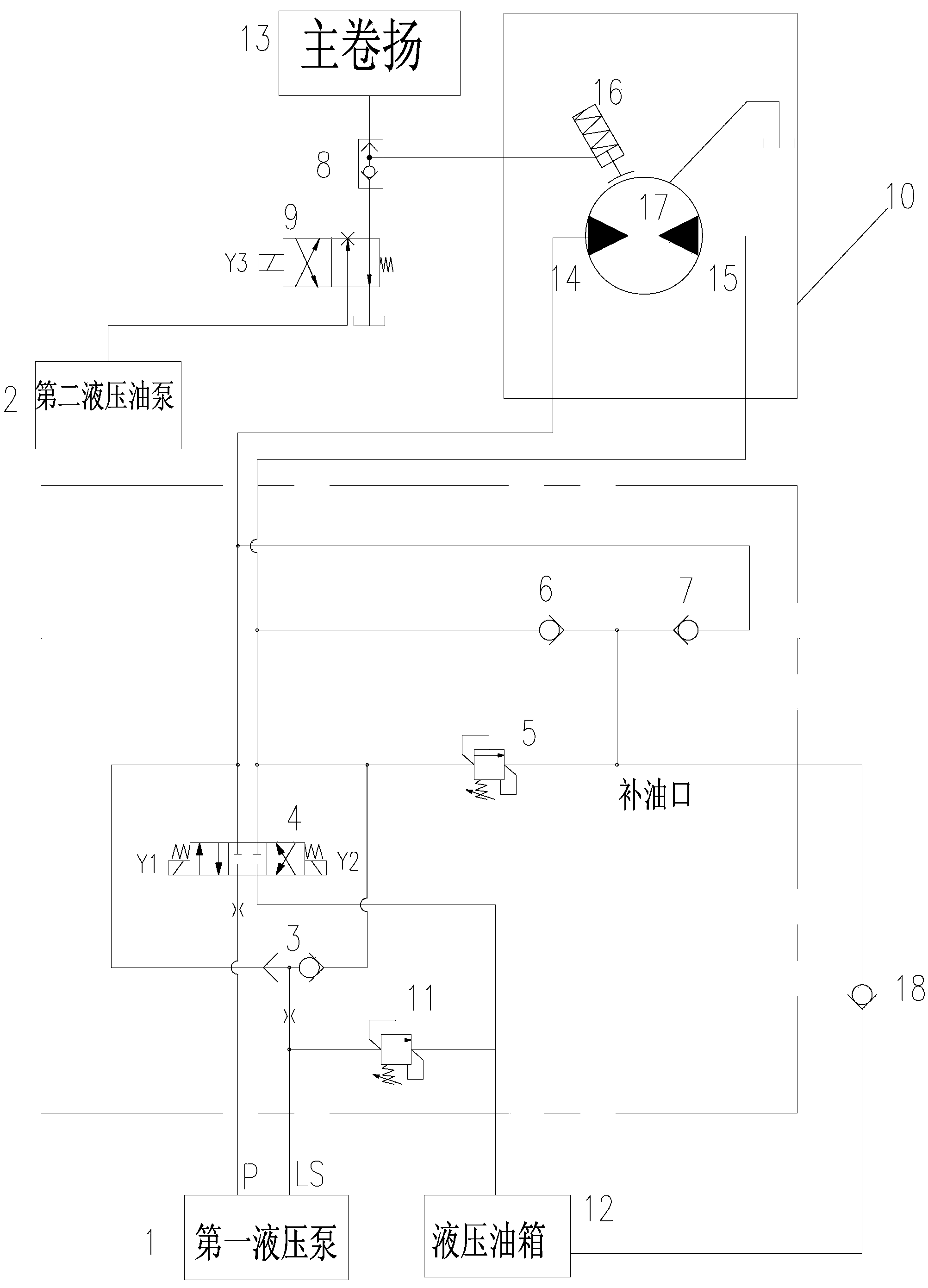
[0049]Such as figure 1 As shown, it is a schematic diagram of the control circuit of the present invention, a pressurization control circuit of the power head of pile machinery, including the first hydraulic pump 1, the second hydraulic pump 2, the first shuttle valve 3, the first solenoid valve 4, the first Relief valve 11, main winch 13, second solenoid valve 9, second shuttle valve 8, pressurized winch 10, hydraulic oil tank 12 and controller;

[0050] The first solenoid valve 4 is a three-position four-way solenoid valve;

[0051] The main hoist 13 refers to the hoist transmission device used to control the up and down movement of the power head, and the pressurization hoist 10 refers to the hoist transmission device used for pressurizing the power head, including a hydraulic motor 17 and a braking mechanism 16. A first oil port 14 and a second oi...


PUM


Abstract

The invention discloses a pressurization control loop and method of a piling machinery power head. The pressurization control loop is a pressurization logic control loop designed through electric hydraulic combined control. The control loop is simple and convenient for a pressurizing winch to coil/uncoil a rope, and convenience in loading and unloading is realized. By the control method, the pressure of pressure oil in the loop is controlled by an overflow valve and a check valve, so that when a main winch hoists, the pressurizing winch can automatically uncoil the rope along the main winch; when the main winch lowers, the speed of the pressurizing winch to coil the rope is perfectly matched with the speed of the pressurizing winch to uncoil the rope; when the pressurizing winch pressurizes, the pressure is controlled by the overflow valve, so that the condition that the pressure of the power head is controllable is realized.

Description

technical field [0001] The invention relates to a pressurization control circuit and method of a power head of a piling machine. Background technique [0002] Pile machinery is widely used in foundation pile construction because of its fast hole forming speed and good pile quality. The drilling operation conditions of pile machinery are harsh and complicated. Under different strata and geology, even the same rock layer will cause changes in the load of pile machinery during drilling due to caves, gaps, interlayers, etc.; therefore, In order to increase the drilling speed and ensure the effective drilling of the drilling rig, it is necessary to ensure that the pressure on the power head has good regulation. The pressure of the power head affects the feed speed of the drill pipe. The change of the pressure of the power head will cause the change of the rotary pressure of the power head, which will affect the drilling efficiency of the pile machine. Therefore, the automatic pr...

Claims


Application Information

Patent Timeline
IPC IPC(8): B66D1/48B66D1/08B66D5/28E21B19/084
Inventor 何清华朱建新曾素钱奂云朱振兴白永安
Owner SUNWARD INTELLIGENT EQUIP CO LTD
Why Eureka
Try Eureka