Powder material cooling system and cooling process thereof

A powder material and cooling system technology, applied in heat exchange equipment, direct contact heat exchangers, fixed tubular conduit components, etc., can solve the problem of low control requirements, powder materials that do not have engineering feasibility, and are not easy to form Stable fluidized bed and other issues to achieve the effect of low control requirements, improved cooling effect, and easy control

Pending Publication Date: 2020-07-10
CHINA CHENGDA ENG
View PDF0 Cites 3 Cited by
  • Summary
  • Abstract
  • Description
  • Claims
  • Application Information

AI Technical Summary

Problems solved by technology

[0009] In order to solve the technical problem that the above-mentioned existing cooling technology is not suitable for some powder materials with small particle size, easy moisture absorption or deterioration, and poor fluidity, which leads to no engineering feasibility, the purpose of the present invention is to provide a powder The purpose of the material cooling system and its cooling process is to use a small amount of gas to carry the high-temperature powder material to flow, so that the solid powder is in a state similar to a high-speed fluid for sufficient heat exchange, so that the heat transfer is mainly convective heat transfer, compared to Powder flow heat transfer, rotary heat transfer, and disc heat transfer have greatly improved the efficiency of powder heat transfer; especially for powders with a particle size of less than 30 μm, it is not easy to form a stable fluidized bed. The air flow controlled by this cooling system The speed is greater than the take-out speed of all particles. The gas-solid two-phase does not need to form a well-defined stable bed. It only needs to ensure that it can flow out from the top through the heat exchange tube to complete the cooling operation. It has low control requirements and can significantly improve cooling. Reliability of technology, while reducing operating costs, significantly improving the economic benefits of enterprises

Method used


Image

  • Powder material cooling system and cooling process thereof
  • Powder material cooling system and cooling process thereof

Examples


Embodiment 1

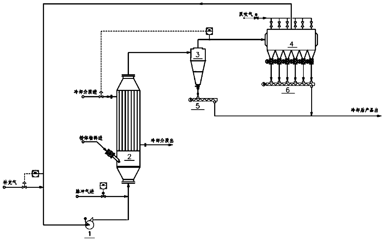
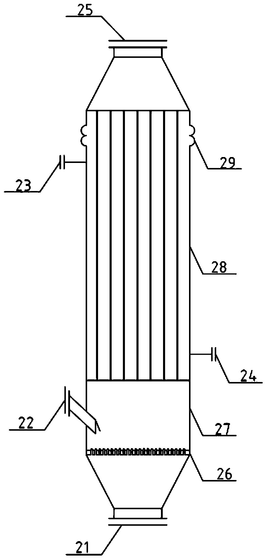
[0042] The embodiment is basically as figure 1 with figure 2 Shown: This embodiment provides a cooling system for powder materials, which can be used in the fields of chemical engineering, inorganic salt industry, metal oxide, metal powder production, etc. Moist or perishable, poor fluidity powder materials have poor cooling effect and are not suitable for engineering implementation, which has good practicability; specifically, such as figure 1 As shown, the cooling system includes a circulating fan 1, a powder fluidized cooler, a cyclone separator 3, a bag filter and a powder conveyor; wherein, the powder fluidized cooler is vertically installed, and the powder fluidized cooling The lower end of the device is provided with a powder material inlet 22, and its top outlet 25 is connected with the inlet of the cyclone separator 3, and the bottom gas inlet 21 of the powder fluidized cooler is connected with the outlet of the circulating fan 1, so that the gas-solid two-phase flo...

Embodiment 2

[0055] On the other hand, this embodiment also provides a cooling process of the powder material cooling system, using the above powder material cooling system, specifically including the steps of starting up and stopping:

[0056] Driving steps:

[0057] Step 1, open the air supply valve on the air supply pipeline, turn on the circulation fan 1, and replace the air in the cooling system; during this process, the circulation fan 1 operates at low load;

[0058] Step 2: Open the feed valve of the powder material inlet 22, and the powder material enters the fluidization chamber 27 of the powder fluidization cooler to form a stable fluidization state, so that the powder material is evenly distributed in the air distribution above plate 26;

[0059] Step 3: Increase the flow rate of the circulating fan 1 and increase the feeding amount of the powder material at the same time. Driven by the carrier gas, the powder material evenly enters the tube side of the shell-and-tube heat exc...


PUM


Abstract

The invention discloses a powder material cooling system and a cooling process thereof, and relates to the technical field of powder material cooling. The system comprises a circulating fan, a powderfluidizing cooler, a cyclone separator, a bag type dust collector and a powder conveyor. An outlet in the top of the powder fluidizing cooler communicates with an inlet of the cyclone separator, and agas inlet in the bottom of the powder fluidizing cooler is connected with an outlet of the circulating fan, so that gas and solid phases flow out of the outlet in the top of the powder fluidizing cooler and enter the cyclone separator; the bottom of the cyclone separator is a cooled product material discharge port, and a tail gas outlet in the top of the cyclone separator is connected with the bag type dust collector; the bag type dust collector is connected to an inlet of the circulating fan, so that the gas collected by the bag type dust collector is recycled as fluidizing gas. By implementing the technical scheme, the technical problem that an existing cooling technology is not applicable to some powder materials small in particle size, likely to absorb moisture or go bad and poor in fluidity can be effectively solved, the reliability of the cooling technology can be remarkably improved, and meanwhile the operation cost is reduced.

Description

technical field [0001] The invention relates to the technical field of powder material cooling, in particular to a powder material cooling system and a cooling process thereof. Background technique [0002] In the production of inorganic salts, metal oxides, and metal powders, it is often necessary to cool the high-temperature powder materials obtained by calcination for packaging and transportation. The traditional powder cooling technology adopts indirect heat exchange of cooling water or direct heat exchange of air / inert gas for cooling, but the inventors of the present application found that the existing powder cooling technologies have their own The limitations of: [0003] 1. Powder flow heat exchanger technology: relying on its own gravity, the high-temperature solid powder flows through the narrow channel of the plate heat exchanger by itself, and conducts indirect heat exchange with the cooling water on the other side to achieve the purpose of cooling the material....

Claims


Application Information

Patent Timeline
Patent Type & Authority Applications(China)
IPC IPC(8): F28C3/16F28D7/16F28F9/00F28F27/00
CPCF28C3/16F28D7/16F28F9/001F28F27/00
Inventor 刘人滔李育亮周彦明刘斌李魁王智拓黄泽茂曾宇峰徐秀海赵雯婷
Owner CHINA CHENGDA ENG
Why Eureka
Try Eureka