Transfer alignment method in polar region based on inverse coordinate system

A technology of inverse coordinate system and transfer alignment, which is applied in the direction of measuring devices, instruments, etc., can solve problems such as inability to perform transfer alignment, and achieve the effect of improving the scope of application

Inactive Publication Date: 2013-12-25
HARBIN ENG UNIV
View PDF2 Cites 10 Cited by
  • Summary
  • Abstract
  • Description
  • Claims
  • Application Information

AI Technical Summary

Problems solved by technology

First, by establishing a new geographic coordinate system based on the inverse coordinate system, the high latitude and polar regions under the traditional coordinate system are converted into the middle and low latitude areas under the inverse coordinate system, and the traditional coordinate system is downloaded to the body by using the idea of ​​mathematical geometry. Convert the position and heading information to the inverse coordinate system, use the obtained relevant navigation information, and use the fast transfer alignment method of speed plus attitude matching to derive the polar area transfer alignment differential equation based on the inverse coordinate system, and establish the velocity error and principal The differential equation of the inertial navigation misalignment angle, and the Kalman filter model is established to filter and estimate the misalignment angle of the main sub-inertial navigation, which overcomes the problem that the ship cannot be transferred and aligned in the polar region to a certain extent, and improves the polar region transmission. Alignment accuracy

Method used


Image

  • Transfer alignment method in polar region based on inverse coordinate system
  • Transfer alignment method in polar region based on inverse coordinate system
  • Transfer alignment method in polar region based on inverse coordinate system

Examples


Embodiment Construction

[0022] The present invention will be described in detail below in conjunction with specific embodiments.

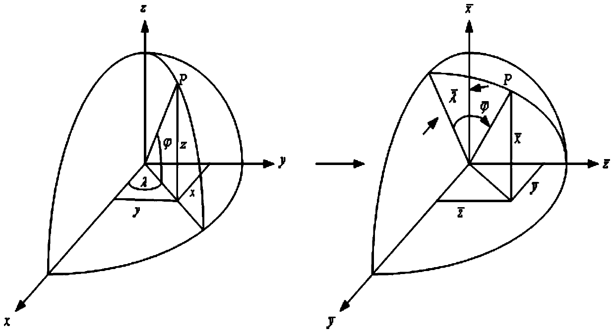
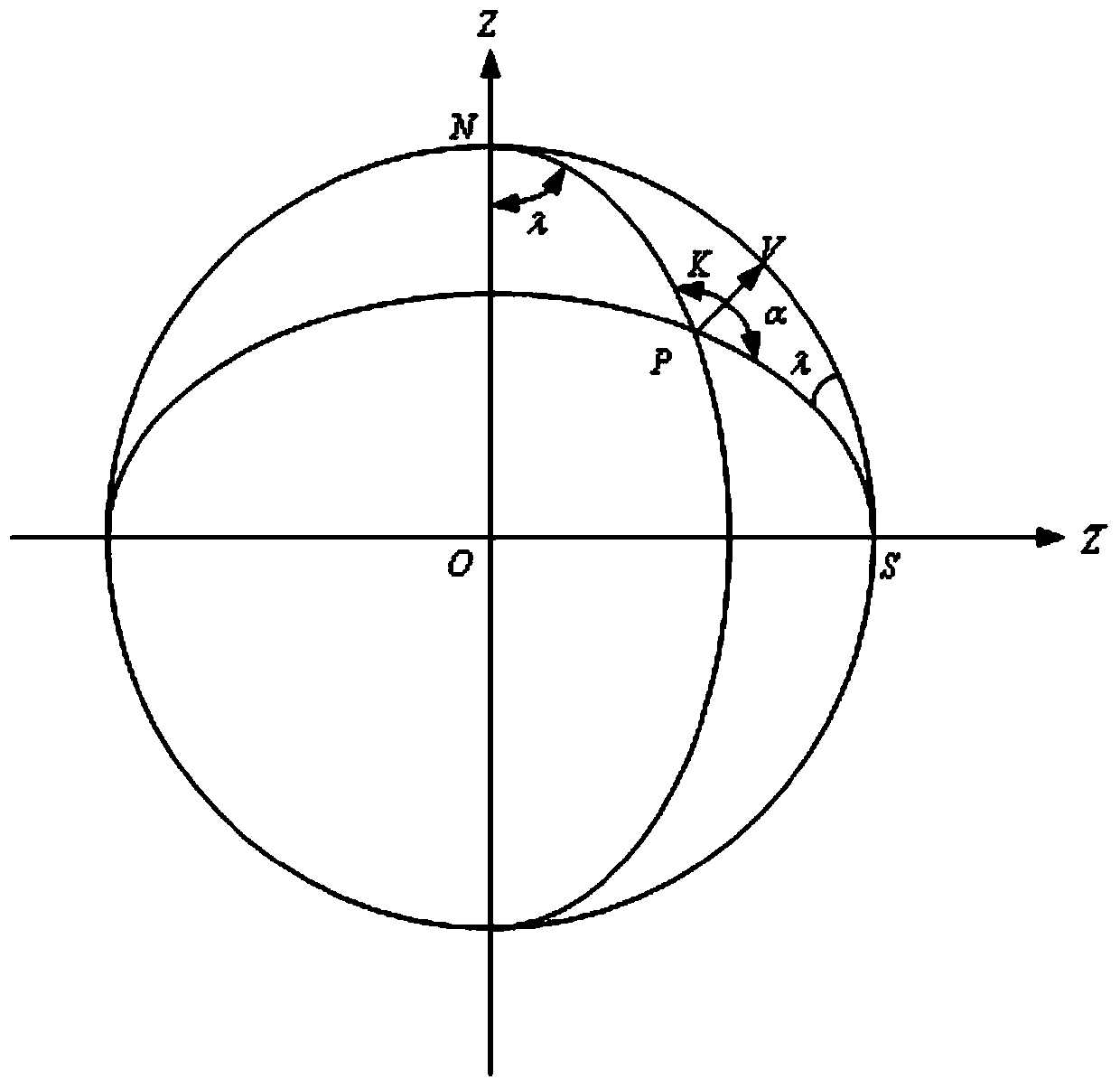
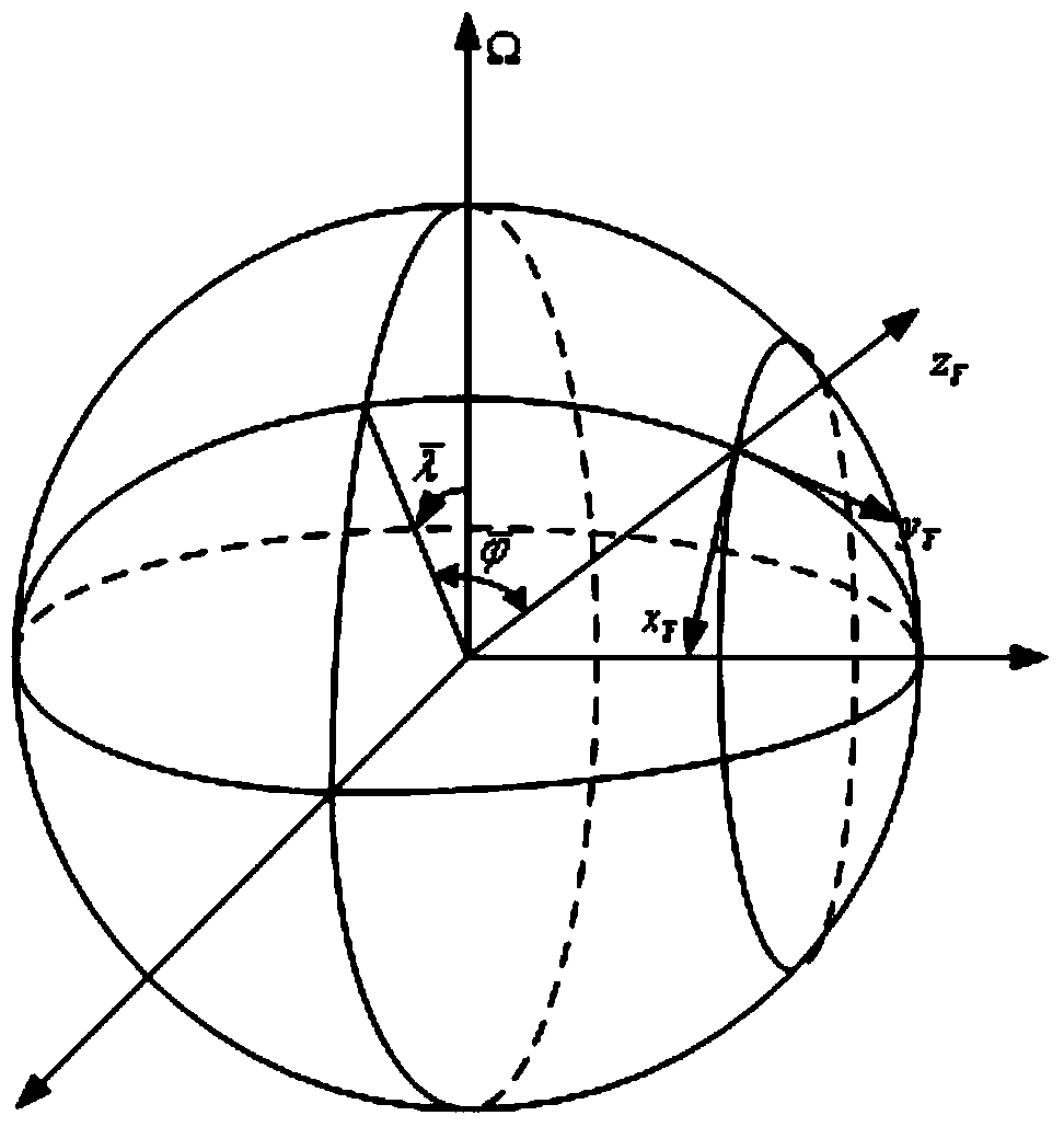
[0023] The specific implementation process of the present invention is to first establish the inverse coordinate system based on the coordinate transformation principle, then establish a new geographic coordinate system based on the inverse coordinate system, and use the coordinate relationship of the carrier between the two coordinate systems and the principle of spherical geometry to obtain the inverse coordinate Based on the navigation information under the system, use the navigation information to establish the speed and attitude error differential equations of the master and sub-inertial navigation, and then use the obtained differential equations to establish the speed plus attitude matching fast transfer alignment state equation and measurement equation, and then design the Karl The filtering model of the Mann filter is used to estimate the misalignment angle betwee...


PUM


Abstract

The invention discloses a transfer alignment method in a polar region based on an inverse coordinate system. The method comprises the steps of taking the earth as a sphere, converting carrier navigation information under the traditional coordinate system into the inverse coordinate system by establishing the inverse coordinate system, obtaining carrier navigation information under a new coordinate system, establishing a new geographic coordinate system based on the inverse coordinate system, establishing a state equation and a measurement equation of transfer alignment under the new coordinate system by establishing a quick velocity and posture transfer alignment matching method, establishing a Kalman filtering equation to estimate a misalignment angle of primary and secondary inertial navigation, and judging the feasibility of the transfer alignment in the polar region. The method solves the problem that the transfer alignment method based on the traditional geographic coordinate system cannot be used during navigation of a ship in the polar region. The method has the characteristics of independence, flexibility, simplicity and certain navigation accuracy, and is more applicable to launch of shipborne weapons in high latitudes and the polar region.

Description

technical field [0001] The invention relates to a transfer alignment method in the polar region based on an inverse coordinate system, which can be used for high-latitude launch of ship-borne weapons in the polar region and energy survey and navigation of the ship in the polar region. Background technique [0002] The transfer alignment technology is a kind of initial alignment of the moving base, and the transfer alignment involves two sets of inertial navigation systems. A set of high-precision inertial navigation system will be installed on ships or aircrafts as the main inertial navigation system (Main Inertial Navigation System abbreviated as MINS) of ships and aircrafts. Shipborne weapons and airborne missiles have their own set of inertial navigation systems, usually their accuracy is not very high, compared to the main inertial navigation system, they are called sub-inertial navigation systems (Slave Inertial Navigation System abbreviated as SINS) . In the strapdow...

Claims


Application Information

Patent Timeline
Patent Type & Authority Applications(China)
IPC IPC(8): G01C25/00
Inventor 孙枫杨祥龙刘新源李敬春李明宇叶攀杨晓龙赵维珩阮双双杨蛟龙
Owner HARBIN ENG UNIV
Why Eureka
Try Eureka