Reactor core with high fast neutron fluence

A fast neutron and fluence rate technology, applied in the direction of moderator/core structure, reactor, nuclear power generation, etc., can solve the problems of limiting core power density and neutron fluence rate level, and achieve enhanced irradiation Capability and application range, high practical value, effect of high irradiation capability

Active Publication Date: 2013-12-25
NUCLEAR POWER INSTITUTE OF CHINA
View PDF10 Cites 26 Cited by
  • Summary
  • Abstract
  • Description
  • Claims
  • Application Information

AI Technical Summary

Problems solved by technology

Compared with the JHR reactor, the lower U-235 enrichment, fuel core uranium density and coolant

Method used


Image

  • Reactor core with high fast neutron fluence
  • Reactor core with high fast neutron fluence
  • Reactor core with high fast neutron fluence

Examples


Example Embodiment

[0032] Example 1:

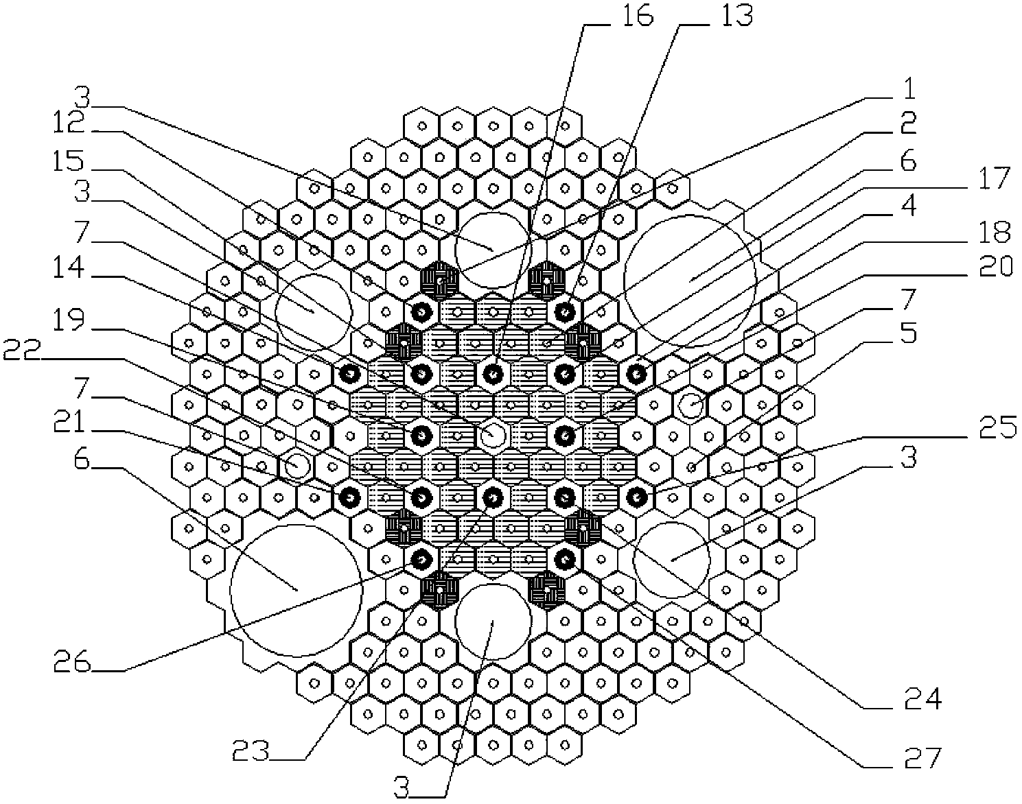
[0033] Such as figure 1 As shown, the high fast neutron fluence rate reactor core of the present invention includes a cobalt target 1, a seven-layer fuel assembly 2, a middle irradiation tunnel 3, a control rod assembly 4, a beryllium assembly 5, a large irradiation tunnel 6 and a small radiation According to the tunnel 7; the seven-layer fuel assembly 2 is a hexagonal sleeve-type fuel assembly, 42 seven-layer fuel assemblies 2 are arranged in a compact ring shape, and there are 6 seven-layer fuel assemblies 2 on the innermost ring. A fast neutron trap is formed in the center, and a small irradiation tunnel 7 is arranged in the fast neutron trap. A higher fast neutron fluence rate can be obtained in the small irradiation tunnel 7; next to the seven-layer fuel assembly 2 A number of hexagonal beryllium components 5 are arranged on the outer side of the ring area. The beryllium components 5 are used as a moderator and a reflective layer to form an inverted neutr...

Example Embodiment

[0034] Example 2:

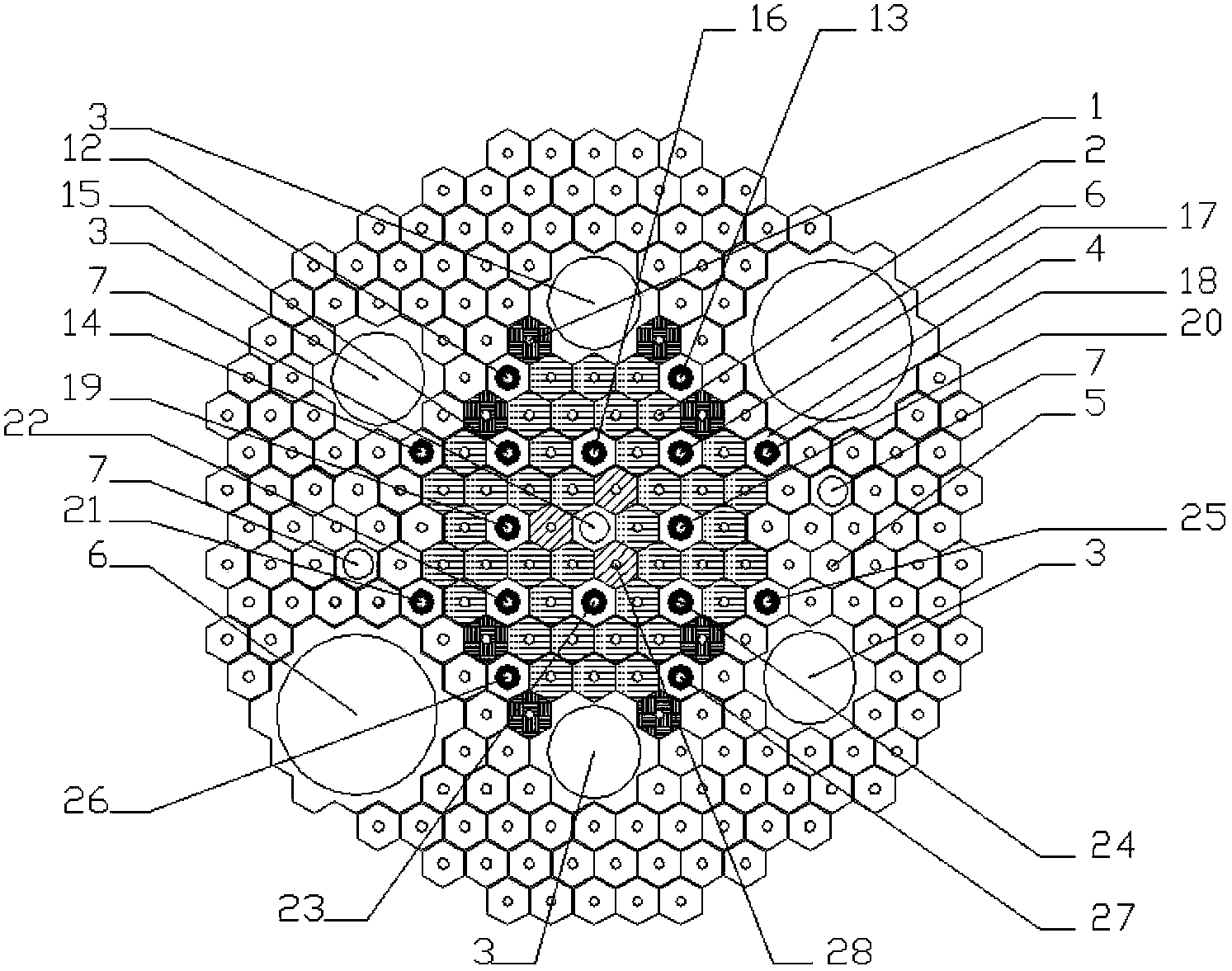
[0035] Such as figure 2 As shown, the high fast neutron fluence rate reactor core of the present invention includes a cobalt target 1, a seven-layer fuel assembly 2, a middle irradiation tunnel 3, a control rod assembly 4, a beryllium assembly 5, a large irradiation tunnel 6, and a small radiation According to the tunnel 7 and the four-layer fuel assembly 28; the seven-layer fuel assembly 2 and the four-layer fuel assembly 28 are both hexagonal tube-in-tube fuel assemblies, 39 seven-layer fuel assemblies 2 and 3 four-layer fuel assemblies 28 are annular and compact Arrangement, three seven-layer fuel assemblies 2 and three four-layer fuel assemblies 28 are arranged at intervals on the innermost ring. A fast neutron trap is formed in the center of its annular area, and a small neutron trap is arranged in the fast neutron trap. Irradiation tunnel 7, high fast neutron fluence rate can be obtained in the small irradiation tunnel 7; a number of hexagonal beryllium...


PUM

PropertyMeasurementUnit
Diameteraaaaaaaaaa
Diameteraaaaaaaaaa
Diameteraaaaaaaaaa

Abstract

The invention belongs to the technical field of nuclear reactor design, and in particular relates to a reactor core with high fast neutron fluence. The reactor core consists of fuel assemblies, control rod assemblies and beryllium assemblies. The plurality of fuel assemblies are hexagonal sleeve type fuel assemblies and in annular compact arrangement; six fuel assemblies are arranged on an innermost ring to form a fast neutron trap at the center of the annular region; the plurality of hexagonal beryllium assemblies are arranged close to the external side of the annular region of the fuel assemblies to form an inverted neutron trap; and the plurality of control rod assemblies are arranged among the fuel assemblies at intervals and in two rows and two columns in a squared shape. The reactor core with high fast neutron fluence satisfies internationally restricted U-235 enrichment degree and requirements of domestic fuel core production and design of coolant flow velocity, and can obtain high fast neutron fluence level in an irradiation tunnel, and enhance and widen irradiation capability and scope of application of a test reactor.

Description

technical field [0001] The invention belongs to the technical field of nuclear reactor design, and in particular relates to a high-fast neutron fluence rate reactor core. Background technique [0002] The development of nuclear power engineering is inseparable from nuclear reactors, and the development of nuclear reactors is inseparable from test reactors. The test reactor plays a very important role in the development of various reactor types. The development trend of modern test reactors is to have high thermal neutron or fast neutron fluence rate and a large number of experimental channels, including a certain number of large-sized channels. An important goal pursued by the advanced test reactor design is a high fast neutron fluence rate. The higher the fast neutron fluence rate in the pile, the shorter the time required for the material irradiation test. For example, the fusion reactor is one of the most promising energy sources in the future, and the materials used i...

Claims


Application Information

Patent Timeline
IPC IPC(8): G21C5/00G21C5/02
CPCY02E30/30
Inventor 王连杰黄世恩魏彦琴夏榜样于颖锐李庆
Owner NUCLEAR POWER INSTITUTE OF CHINA
Why Eureka
Try Eureka