Bionic piezoelectric foot type driver

A driver, bionic technology, applied in the direction of generator/motor, piezoelectric effect/electrostrictive or magnetostrictive motor, electrical components, etc., can solve the problems of low transmission efficiency, small stroke, complex structure, etc. The effect of large stroke, simple structure and simple control system

Inactive Publication Date: 2013-12-25
ZHEJIANG NORMAL UNIVERSITY
View PDF7 Cites 21 Cited by
  • Summary
  • Abstract
  • Description
  • Claims
  • Application Information

AI Technical Summary

Problems solved by technology

[0008] The invention provides a bionic piezoelectric foot driver to solve the problems of low transmission efficiency, small stroke and complex structure of the above-mentioned driver

Method used


Image

  • Bionic piezoelectric foot type driver
  • Bionic piezoelectric foot type driver
  • Bionic piezoelectric foot type driver

Examples


Embodiment Construction

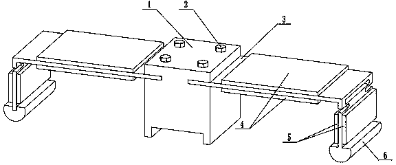
[0016] Such as image 3 and Figure 4 As shown, two driving feet of the driver are arranged symmetrically at both ends of the driver main body 1, and the driving feet of the driver are composed of a metal substrate 3, two piezoelectric ceramic wafers one 4, two piezoelectric ceramic wafers two 5 and a cylindrical The friction block 6 is composed of a metal substrate 3 composed of a beam and a vertical beam. One end of the beam of the metal substrate 3 is fixed on the driver main body 1 through a screw 2. Two piezoelectric ceramic wafers 4 are symmetrically glued on the upper and lower sides of the beam of the metal substrate 3. Two piezoelectric ceramic chips 25 are symmetrically bonded to the left and right sides of the vertical beam of the metal substrate 3, and a cylindrical friction block 6 is affixed to one end of the vertical beam of the metal substrate 3.

[0017] Way of working:

[0018] When the driver works, the period of the driving electric field signal acting on...


PUM


Abstract

The invention belongs to a bionic piezoelectric foot type driver and belongs to the field of micro-mechanical and electronic engineering. Two driver driving feet are symmetrically arranged at two ends of a driver body, and each driving foot of the driver consists of a metal substrate, two first piezoelectric ceramic wafers, two second piezoelectric ceramic wafers and a cylindrical friction block. The metal substrate consists of a cross beam and a vertical beam, wherein one end of the cross beam of the metal substrate is fixedly connected onto the driver body through a screw, the two first piezoelectric ceramic wafers are symmetrically bonded on the upper and lower faces of the cross beam of the metal substrate, the two second piezoelectric ceramic wafers are symmetrically bonded on the left and right faces of the vertical beam of the metal substrate, and one end of the vertical beam of the metal substrate is fixedly connected with the cylindrical friction block. The bionic piezoelectric foot type driver has the advantages that the driving feet of the driver can imitate leg actions of walking animals, the driver is novel in structure, large in stroke and simple in structure, and a control system is simple.

Description

technical field [0001] The invention belongs to the field of micromechanical and electronic engineering, and in particular relates to a piezoelectric foot driver. Background technique [0002] With the development of science and technology, nanotechnology plays an increasingly important role in the mechanical field. The research on the micro-displacement system has attracted the attention of scholars at home and abroad, and various micro-drivers with functions of precise driving, precise measurement and precise positioning have been developed successively. Because piezoelectric elements have the characteristics of small size, high displacement resolution, fast frequency response, no electromagnetic interference, and no noise, piezoelectric micro-actuators using such elements as driving sources have attracted more and more attention. [0003] The currently developed micro-drivers using piezoelectric elements as the driving source are mainly divided into the following fou...

Claims


Application Information

Patent Timeline
Patent Type & Authority Applications(China)
IPC IPC(8): H02N2/00H02N2/04
Inventor 程光明李新辉李晓旭胡意立温建明阚君武张忠华曾平
Owner ZHEJIANG NORMAL UNIVERSITY
Why Eureka
Try Eureka