
System and method for frequency channel packaging background processing

A background processing and channel technology, applied to TV system components, color TV components, TV, etc., can solve the problem of affecting the rendering ability of the broadcast server, occupying large system resources, and reducing the stability and reliability of the broadcast system And other issues

Active Publication Date: 2013-12-25
BEIJING DAYANG TECH DEV
View PDF2 Cites 4 Cited by
  • Summary
  • Abstract
  • Description
  • Claims
  • Application Information

AI Technical Summary

Problems solved by technology

[0004] The traditional way of broadcasting channels and information will take up a lot of system resources. With the widespread application of high-definition and 4K ultra-high-definition videos, collecting each frame of video into the memory and performing GPU rendering processing will occupy a large amount of rendering and broadcasting servers. System resources, while occupying a large amount of system memory resources and GPU resources, will greatly affect the rendering capabilities of the broadcast server
The broadcasting method of DVE packaging for the background video of the channel packaging system is only a small part of the application, and in most cases, the broadcasting only needs to superimpose graphics and texts on the background video, and collect each frame of the background video into the memory. The method of rendering through the GPU and returning to the IO card for broadcasting reduces the stability and reliability of the entire broadcasting system

Method used


Image

  • System and method for frequency channel packaging background processing
  • System and method for frequency channel packaging background processing

Examples


Embodiment 1

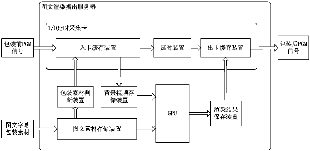
[0022] This embodiment is a system for channel packaging background processing, such as figure 1 shown. The present embodiment comprises: the GPU that is arranged in the image-text rendering server, and the described image-text rendering and playing server is also provided with an I / O delay acquisition card, and the I / O delay acquisition card is set according to this The connected card-in buffer device for receiving the PGM signal before packaging, the delay device, and the card-out buffer device for outputting the PGM signal after packaging. Described picture-text rendering server is provided with the picture-text material storage device that receives picture-text subtitle packing material, and described picture-text material packing device is connected with described GPU, and described picture-text material storage device also judges with packing material The device is connected, the packaging material judging device is connected to the card-in buffer device, the card-in bu...

Embodiment 2

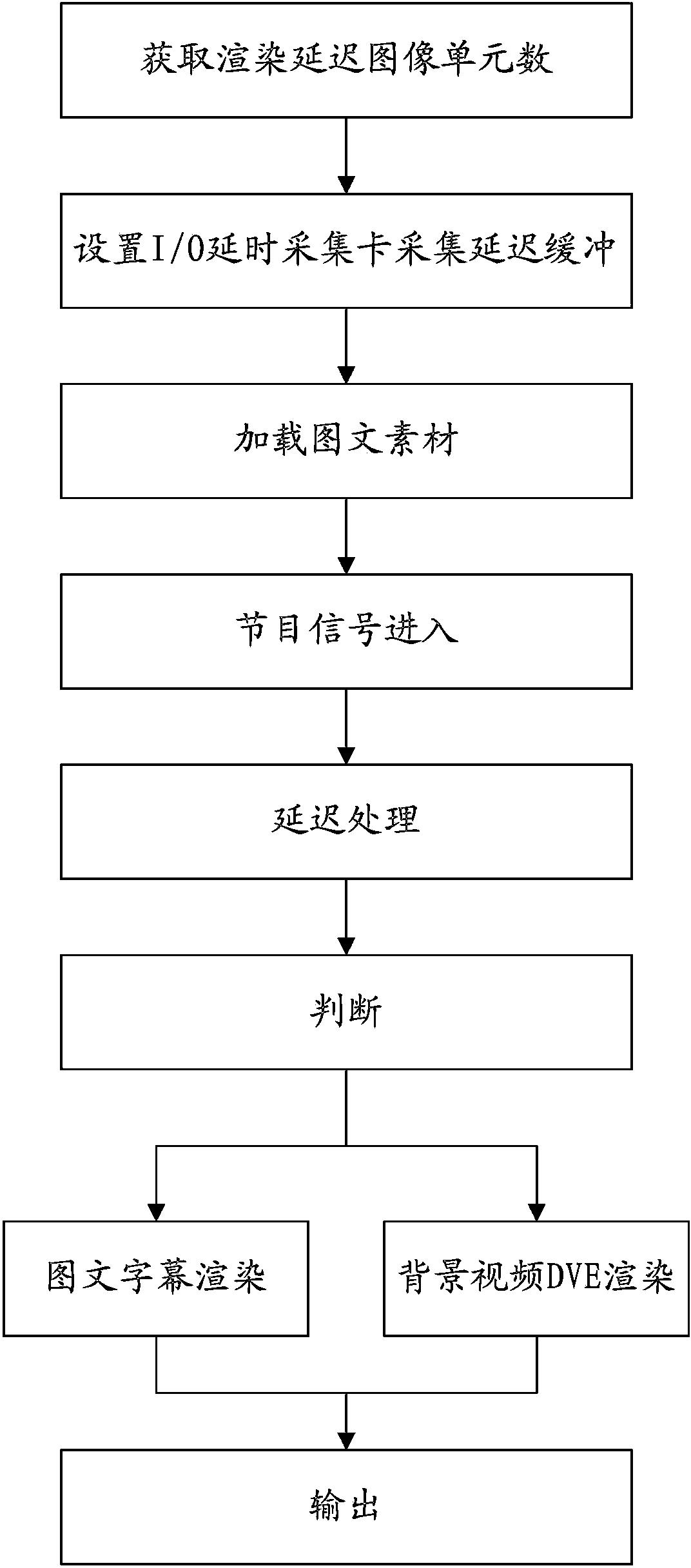
[0030] This embodiment is a method for channel packaging background processing using the system described in Embodiment 1. The process is as followsfigure 1 shown. The steps of the method described in this embodiment are as follows:

[0031] The step of obtaining the number of image units of rendering delay: used to obtain the number of image units of real-time rendering delay according to the rendering control process of the graphic rendering and playout server. The image unit described in this embodiment refers to a frame or a field of an image, that is, a frame or a field of an image is collectively referred to as an image unit. In terms of acquisition mode, frame mode or field mode can be adopted, both of which are collectively referred to as image unit acquisition mode. This step is to obtain a more accurate delay time length. The delay time is usually determined according to the rendering process. If the rendering process is relatively simple, the delay time can be sho...

Embodiment 3

[0044] This embodiment is an improvement of the first embodiment, and is a refinement of the first embodiment regarding the acquisition mode. The acquisition mode described in this embodiment is one of the field acquisition mode and the frame acquisition mode.

[0045] Frame acquisition means that the I / O card processes the background video in units of frames, that is, the card input buffer device, delay processing device and card output buffer device in the I / O card all use one frame of image as a processing unit.

[0046] Field acquisition means that the I / O card processes the background video in units of fields, that is, the card input buffer device, delay processing device and card output buffer device in the I / O card all use a field image as a processing unit.

[0047] The selection of the I / O card acquisition method is related to the format of the input background video. If the input background video is progressive scan and one frame of image is scanned each time, the I / O...


PUM


Abstract

The invention relates to a system and method for frequency channel packaging background processing. The method comprises the following steps of rendering delay image unit number obtaining, collecting delay buffering by arranging an I / O delay collecting card, image-text material loading, program signal entering, delay processing, judging, image-text subtitle rendering, background video DVE rendering and outputting. According to the system and method for frequency channel packaging background processing, delay time is rendered in real time according to an image-text rendering broadcast server; collection delay is set inside the I / O delay collecting card; buffering processing is conducted on an input signal source video; under the condition that image-text subtitles need to be overlapped on a background video, each background video image unit undergoes delay buffering control inside the I / O delay collecting card and is overlapped with a GPU rendering result and directly output; under the condition that DVE processing is needed, each background video image unit enters the I / O delay collecting card to undergo delay processing and is collected into a memory immediately, and then returns to the I / O delay collecting card after undergoing GPU rendering, and therefore seamless connection is realized.

Description

technical field [0001] The present invention relates to a system and method for channel packaging background processing, a system and method for video image processing, and a system and method for processing video signals broadcast by TV stations. Background technique [0002] With the popularization of high-definition TV, more and more TV programs use high-definition pre-production, high-definition broadcast, high-definition live broadcast and other high-definition program production and broadcast. The improvement in picture quality of high-definition programs benefits from the multiplication of picture pixels. The increase of pixels doubles the number of video calculations, which poses a new problem for the production and broadcast of digital high-definition. If you still use the equipment of the SD era, it is a very clumsy way to simply increase the hardware capacity and computing speed of the equipment. If high-definition programs are broadcast regardless of cost, this...

Claims


Application Information

Patent Timeline
IPC IPC(8): H04N5/272H04N5/14
Inventor 郭文佳孔鑫兰建立张孜恒骆萧萧
Owner BEIJING DAYANG TECH DEV
Learn More