Double-action double-angle lateral shaping mechanism
A double-angle, side-shaping technology, applied in forming tools, metal processing equipment, manufacturing tools, etc., to achieve the effect of saving the number of processes, saving mold costs, and saving stamping time
Active Publication Date: 2014-01-01
SHANGHAI HUAZHUANG MOLD
View PDF9 Cites 9 Cited by
- Summary
- Abstract
- Description
- Claims
- Application Information
AI Technical Summary
Problems solved by technology
[0003] The applicant has applied for a patent application number: 201110241023.8, the subject of which is "a double-movable side shaping mechanism for outer cover punch". Solve the problem that the part cannot be taken out after the negative corner flanging of the part, and the problem of the concave surface forming in the process of the negative corner flanging of the part cannot be solved
Method used
View moreImage
Smart ImageViewing Examples

Examples
Embodiment Construction
Login to View More PUM
 Abstract
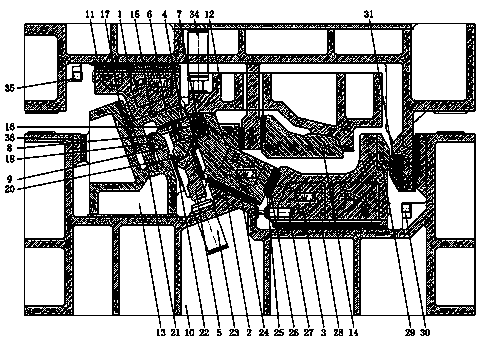
The invention relates to a double-action double-angle lateral shaping mechanism which comprises a drive part and a movable male die working part. The drive part is an upper die of a punching device. The upper die is provided with a drive face, an insertion type guide plate is disposed at the front end of the drive face, a vertical face is disposed on the rear side of the upper die, and a mounting face and a mounting guide plate are disposed on the vertical face. When an upper die lateral shaping insert completes work, two upper die wedge drive blocks mounted on the upper die lateral shaping insert starts to work at two different angles. Advance and retreat sequence of wedges is important, the upper die lateral shaping insert starts to work when a movable male die slider and a lower die auxiliary pressing plate are in place, and when the upper die lateral shaping insert completes work, the upper die wedge drive blocks mounted on the upper die lateral shaping insert starts to work. Wedges of different angles are mounted on the wedges, and two working directions are provided. The movable die working part comprises various drive blocks, a nitrogen cylinder, a pressing plate, a balance cushion block, an insertion type guide plate and a wear-resistant plate.
Description
Technical field: [0001] The invention relates to a cold stamping die for an inner and outer cover part of an automobile, in particular to a double-action double-angle side shaping mechanism. Background technique: [0002] With the development of the automobile industry and the maturity of the stamping process, the profile of many stamping parts is very complex, and some concave profiles on the flange surface with negative angles are difficult to realize in the existing structure. Especially when the specific production line cannot be satisfied, because the number of stamping machine tools is not enough, it is urgently hoped that a technology can meet the customer's production line and not increase the number of molds on the basis of no stamping process, but products with negative angle flanging A part with a concave surface on the surface. [0003] The applicant has already applied for a patent application number: 201110241023.8, the subject of which is "a double-movable ...
Claims
Login to View More Application Information
Patent Timeline
 Patent Type & Authority Applications(China)
IPC IPC(8): B21D37/10
Inventor 崔林王利军张小卫
Owner SHANGHAI HUAZHUANG MOLD
Features
- R&D
- Intellectual Property
- Life Sciences
- Materials
- Tech Scout
- Unparalleled Data Quality
- Higher Quality Content
- 60% Fewer Hallucinations
Learn More Browse by: Latest US Patents, China's latest patents, Technical Efficacy Thesaurus, Application Domain, Technology Topic, Popular Technical Reports.
© 2025 PatSnap. All rights reserved.Legal|Privacy policy|Modern Slavery Act Transparency Statement|Sitemap|About US| Contact US: help@patsnap.com