
Pipe clamp blanking-punching compound die

A blanking and punching, composite mold technology, applied in the direction of forming tools, manufacturing tools, metal processing equipment, etc., can solve the problems of increasing the work intensity of workers, high frequency of edge grinding, increasing factory costs, etc., to achieve reasonable improvement. performance and stability, reducing the frequency of flat grinding, and reducing carbon emissions

Inactive Publication Date: 2014-01-01
DALIAN YILIAN METAL FORMING
View PDF9 Cites 0 Cited by
  • Summary
  • Abstract
  • Description
  • Claims
  • Application Information

AI Technical Summary

Problems solved by technology

[0002] In the existing technology of our factory, for the processing of pipe clamps, two different processes of blanking and punching are required to use two different molds, namely the blanking mold and the punching mold. At the same time, the positioning accuracy of the existing mold is low. The frequency of edge grinding is high, which not only increases the work intensity of workers, reduces work efficiency, but also increases the cost of the factory

Method used


Image

  • Pipe clamp blanking-punching compound die
  • Pipe clamp blanking-punching compound die

Examples


Embodiment Construction

[0018] The present invention is further described below in conjunction with specific embodiment:

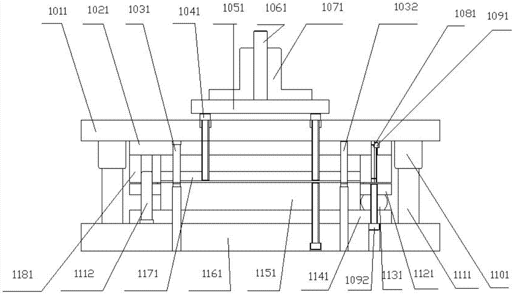
[0019] A pipe clamp blanking and punching composite die, including an upper template 1011, a punch fixing plate 1021, a punching punch I 1031, a punching nail 1041, a punching plate 1051, a punching rod 1061, a mold handle 1071, a punching punch II 1032, and a pin 1081, screw Ⅰ 1091, guide sleeve 1101, guide post Ⅰ 1111, unloading plate 1121, rubber 1131, screw Ⅱ 1092, convex and concave mold fixing plate 1141, convex and concave mold 1151, lower template 1161, material block 1171, guide post Ⅱ 1112, concave mold 1181 ;

[0020] One end of the mold handle 1071 is provided with a cylindrical groove, one end of the punch rod 1061 is inserted into the cylindrical groove, and the other end protrudes from the opening of the cylindrical groove, and the protruding part is higher than the upper surface of the mold handle 1071. The lower end surface of the beating rod 1061 is connected w...


PUM


Abstract

A pipe clamp blanking-punching compound die comprises an upper die plate, a male die fixing plate, a punching male die I, a material ramming pin, a material ramming plate, a material ramming rod, a die shank, a punching male die II, a pin, a screw I, a guide sleeve, a guide column I, a discharging plate, rubber, a screw II, a punch-die fixing plate, a punch-die, a lower die plate, a material ramming block, a guide column II and a female die; one end of the material ramming pin is connected with the lower side of the material ramming plate, the other end of the material ramming pin sequentially penetrates through the upper die plate, the male die fixing plate and the female die from top to bottom and is embedded into the material ramming block, one end of the male die fixing plate enables the female die to be fastened at the lower end of the male die fixing plate through the pin and the screw I, and the female die is provided with a guide hole. When the pipe clamp blanking-punching compound die is applied, a pipe clamp blanking process and a punching process are completed in one procedure simultaneously, one process die is omitted, work efficiency is improved, and cost is lowered.

Description

technical field [0001] The invention relates to the production of mechanical workpieces, in particular to a composite mold for pipe clip blanking and punching. Background technique [0002] In the existing technology of our factory, for the processing of pipe clamps, two different processes of blanking and punching are required to use two different molds, namely the blanking mold and the punching mold. At the same time, the positioning accuracy of the existing mold is low. The frequency of edge grinding is high, which not only increases the work intensity of workers, reduces work efficiency, but also increases the cost of the factory. Contents of the invention [0003] In order to solve the above-mentioned problems in the prior art, the present invention integrates the original blanking and punching dies, improves the die structure, and designs a blanking and punching composite die in which the two processes of blanking and punching are carried out simultaneously. [0004...

Claims


Application Information

Patent Timeline
IPC IPC(8): B21D37/10C21D8/00
Inventor 孙冬生范久卫
Owner DALIAN YILIAN METAL FORMING
Learn More