
Pipe clamp stretching mold

A technology for drawing dies and pipe clamps, which is applied in the field of pipe clamp drawing dies, can solve problems such as uneven distribution of blank-holding force, uneven marks on the surface of pipe clamps, and insufficient stability of blank-holding force, so as to improve rationality and stability , good fluidity and stable blank holder force

Inactive Publication Date: 2014-01-08
DALIAN YILIAN METAL FORMING
View PDF7 Cites 5 Cited by
  • Summary
  • Abstract
  • Description
  • Claims
  • Application Information

AI Technical Summary

Problems solved by technology

[0002] During the stretching process of the pipe clamp produced by our factory, due to the structural design defect of the mold, the mold positioning accuracy is low, the blankholder force acting on the blankholder ring is not evenly distributed, and the blankholder force is not stable enough, and the pipe clamp appears. Obvious uneven marks on the clamp surface, and low smoothness

Method used


Image

  • Pipe clamp stretching mold
  • Pipe clamp stretching mold

Examples


Embodiment Construction

[0017] The present invention is further described below in conjunction with specific embodiment:

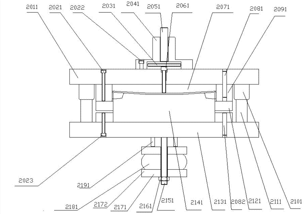
[0018] A pipe clamp stretching die, comprising an upper template 2011, screw I 2021, screw II 2022, a beating plate 2031, a mold handle 2041, a beating rod 2051, a beating nail 2061, a beating block 2071, a pin I 2081, a die 2091, Guide sleeve 2101, guide post 2111, blank holder ring 2121, pin Ⅱ 2082, lower template 2131, punch 2141, screw 2151, nut 2161, push plate Ⅰ 2171, push plate Ⅱ 2172, rubber 2181, push rod 2191, screw Ⅲ 2023 ;

[0019] The mold handle 2041 is installed above the upper template 2011 through the screw II 2022. One end of the mold handle 2041 is provided with a cylindrical groove, and the other end is provided with a square groove. One end of the punch rod 2051 is embedded in the cylindrical groove. The other end protrudes from the opening of the cylindrical groove, and the protruding part is higher than the upper end surface of the mold handle 2041, and th...


PUM


Abstract

The invention discloses a pipe clamp stretching mold. The pipe clamp stretching mold comprises an upper template, a screw I, a screw II, a material-hitting plate, a mold handle, a material-hitting rod, a material-hitting nail, a material-hitting block, a pin I, a hollowing mold, a guide sleeve, a guide column, an edge-pressing ring, a pin II, a lower template, a terrace mold, a screw rod, a nut, a material-pushing plate I, a material-pushing plate II, rubber, a material-pushing rod and a screw III. The upper template is connected with the pin I and the hollowing mold below the pin I through the screw I. The guide sleeve is fixed to the lower portion of the upper template, the guide column is fixedly arranged below the lower template, and the guide column is matched with the guide sleeve in a relatively-sliding mode. The lower template is connected with the terrace mold above the lower template through the screw III, and the edge-pressing ring is arranged at the outer side of the terrace mold in a sleeved mode. According to the application of the pipe clamp stretching mold, edge-pressing force is stable and the edge-pressing force is evenly distributed during the stretching forming process, material flowing performance is good, the surface of a finished product is smooth, and no obvious convex and concave marks exist.

Description

technical field [0001] The invention relates to the production of mechanical workpieces, in particular to a pipe clamp stretching die. Background technique [0002] During the stretching process of the pipe clamp produced by our factory, due to the structural design defect of the mold, the mold positioning accuracy is low, the blankholder force acting on the blankholder ring is not evenly distributed, and the blankholder force is not stable enough, and the pipe clamp appears. There are obvious uneven marks on the surface of the clip, and the smoothness is low. Contents of the invention [0003] In order to solve the above problems in the prior art, the present invention adopts the following technical solutions: [0004] A pipe clamp drawing die, comprising an upper template, screw I, screw II, punching tray, mold handle, punching rod, punching nail, punching block, pin I, die, guide sleeve, guide post, press Edge ring, pin II, lower template, punch, screw, nut, push plat...

Claims


Application Information

Patent Timeline
IPC IPC(8): B21D37/10B21D37/01B21D22/22C21D8/00
Inventor 孙冬生范久卫
Owner DALIAN YILIAN METAL FORMING
Learn More