Connecting rod big-end hole turning clamp

A technology of large head holes and fixtures, applied in the directions of clamping, manufacturing tools, supports, etc., can solve problems such as low work efficiency, and achieve the effect of improving work efficiency, improving work efficiency, and shortening clamping and disassembly time.

Inactive Publication Date: 2014-01-01
LIUZHOU MINGYU MACHINERY
View PDF8 Cites 6 Cited by
  • Summary
  • Abstract
  • Description
  • Claims
  • Application Information

AI Technical Summary

Problems solved by technology

The big head hole clamp for connecting rod has the following disadvantages in the production process: When clamping the connecting rod, after the small end hole of the connecting rod is inserted into the small end positioning pin, the big end of the connecting rod rests on the big end support block and is tightened separately. Four compression screws on the top of the cover, two sides of the cover and the pressure plate; it takes more than 20 seconds to clamp and dismantle the connecting rod, but it only takes more than 10 seconds to close the big head hole, and it takes about 1 minute Only 2 connecting rod big holes can be processed, more than 800 connecting rod big holes can be processed in a single shift, and the work efficiency is low

Method used


Image

  • Connecting rod big-end hole turning clamp
  • Connecting rod big-end hole turning clamp
  • Connecting rod big-end hole turning clamp

Examples


Embodiment Construction

[0015] The present invention will be described in further detail below in conjunction with accompanying drawing embodiment:

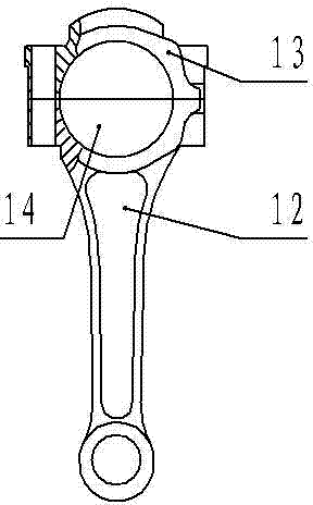
[0016] Such as figure 1 Shown is the connecting rod that needs to be clamped and positioned in this embodiment, including the connecting rod body 12 and the cover body 13. After the connecting rod body 12 and the cover body 13 are combined, there is a big hole 14, which is the hole that needs to be processed.

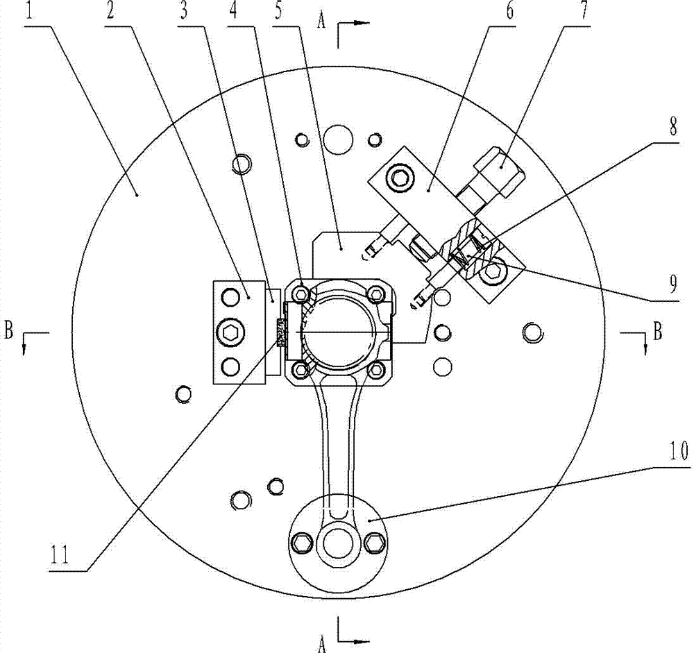
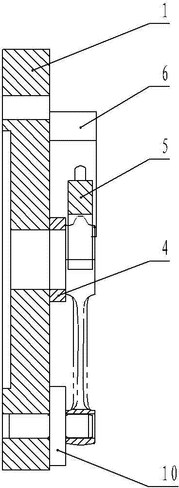
[0017] Such as figure 2 , image 3 , Figure 4 The big head hole clamp for connecting rods shown in the figure includes a clamp body 1 equipped with a small head positioning pin 10 and a big end support block 4, and the clamp body 1 is equipped with a side positioning block 3 and a side clamp on the periphery of the big end support block 4, respectively. A tightening device, an alloy spacer 11 is inlaid on the end surface of the side positioning block 3 near the big head support block 4, and the side positioning block 3 is installed on the cl...


PUM


Abstract

The invention discloses a connecting rod big-end hole turning clamp, and relates to the technical field of machining process technology equipment manufacturing. The connecting rod big-end hole turning clamp comprises a clamp body which is provided with a small-end locating pin and big-end supporting blocks. The clamp body is provided with a side locating block and a side clamping device respectively on the peripheries of the big-end supporting blocks. The side clamping device comprises a side clamping base and a side clamping block which is movably arranged on the side clamping base and provided with a V-shaped working surface, the side clamping base is provided with a puller bolt which penetrates through the side clamping base and is connected with the side clamping block in an abutting mode through threads, and the included angle of the V-shaped working surface of the side clamping block is 90 degrees. Compared with the prior art, when the connecting rod big-end hole turning clamp is used for clamping a connecting rod, after the small-end locating pin is sleeved into a small-end hole of the connecting rod, the puller bolt only needs to be screwed, the connecting rod can be dismantled only by the way that the puller bolt is loosened, clamping time and dismantling time are shortened, and working efficiency is greatly improved.

Description

technical field [0001] The invention relates to the technical field of mechanical processing equipment manufacturing, in particular to a fixture used for processing the big end hole of a connecting rod. Background technique [0002] The connecting rod is a rod whose two ends are respectively hinged with the active and driven components to transmit motion and force. The big head and the small head of the connecting rod are respectively provided with holes hinged with the driving or driven member. Usually, the processing method for the big head hole of the connecting rod is: first cut the big head of the connecting rod radially into the connecting rod body and the cover body; process the joint surfaces of the two respectively, and then cut the connecting rod body and the cover body Carry out turning processing on the big end hole of the connecting rod through the body combination. When performing combined processing on the big end of the connecting rod, it is necessary to us...

Claims


Application Information

Patent Timeline
Patent Type & Authority Applications(China)
IPC IPC(8): B23Q3/00
CPCB23Q3/062
Inventor 梅春锋
Owner LIUZHOU MINGYU MACHINERY
Why Eureka
Try Eureka