
Anti-scrap protective cover and machining center

A technology of machining center and protective cover, which is applied in the direction of metal processing equipment, metal processing machinery parts, manufacturing tools, etc., can solve the problem of large space, and achieve the effect that the structure occupies a small space and is easy to slip

Inactive Publication Date: 2014-01-01
SANY GRP
View PDF7 Cites 5 Cited by
  • Summary
  • Abstract
  • Description
  • Claims
  • Application Information

AI Technical Summary

Problems solved by technology

This type of shield has a simple structure and is widely used, but the horizontal movement of this shield has obvious disadvantages, such as the minimum compression amount occupying a large amount of machine travel and space.

Method used


Image

  • Anti-scrap protective cover and machining center
  • Anti-scrap protective cover and machining center
  • Anti-scrap protective cover and machining center

Examples


Embodiment Construction

[0024] The following will clearly and completely describe the technical solutions in the embodiments of the present invention with reference to the accompanying drawings in the embodiments of the present invention. Obviously, the described embodiments are only some, not all, embodiments of the present invention. Based on the embodiments of the present invention, all other embodiments obtained by persons of ordinary skill in the art without creative efforts fall within the protection scope of the present invention.

[0025] It should be noted that, in the case of no conflict, the embodiments of the present invention and the features in the embodiments can be combined with each other.

[0026] Embodiments of the present invention will be specifically explained below in conjunction with the accompanying drawings.

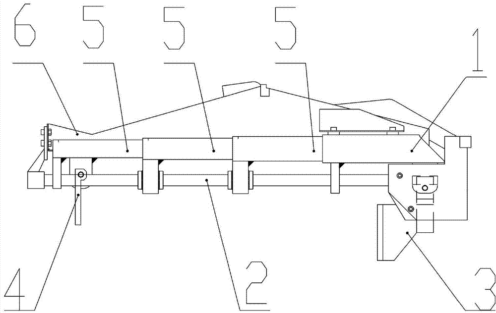
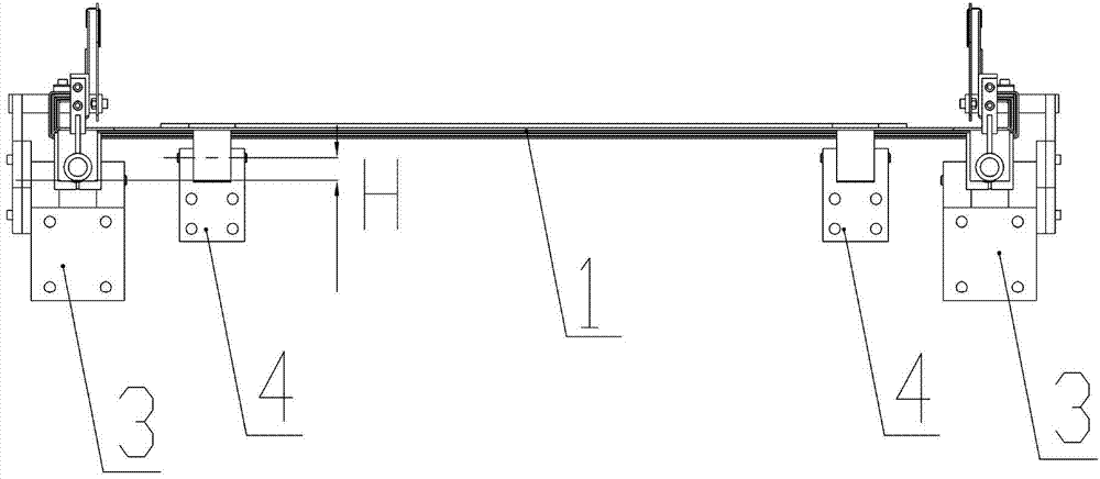
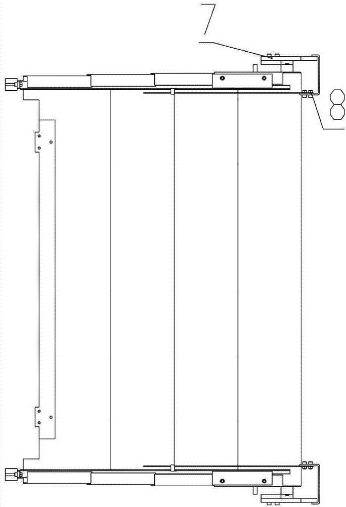
[0027] Such as figure 1 A chip protection cover according to an embodiment of the invention shown in , is suitable for a machining center. A machining center include...


PUM


Abstract

The invention discloses an anti-scrap protective cover and a machining center, and belongs to the field of machine manufacturing. The anti-scrap protective cover is applicable to the machining center. The machining center comprises a lathe bed and a stand column which moves relative to the lathe bed. The anti-scrap protective cover comprises a body 1, a supporting shaft 2, a first hinge 3 and a second hinge 4. The body 1 comprises a plurality of pulling plates 5 which are mutually sleeved in an embedded mode, are arranged on the supporting shaft 2 and can slide along the supporting shaft 2. The first hinge 3 and the second hinge 4 respectively comprise one end and the other end which mutually rotate. The one end of the first hinge 3 is connected with the one end of the body 1. The other end of the first hinge 3 is connected with the lathe bed. The one end of the second hinge 4 is connected with the other end of the body 1. The other end of the second hinge 4 is connected with the stand column. According to the technical scheme of the anti-scrap protective cover and the machining center, by the adoption of linear extension and retraction and the rotational motion at the two ends, the anti-scrap protective cover can turn over by a certain angle, the structure is compact, iron scraps are not easily accumulated, and the movement is flexible.

Description

technical field [0001] The invention belongs to the field of mechanical equipment manufacturing, and relates to a protective cover, in particular to an anti-dust protective cover and a machining center. Background technique [0002] The main function of the inner cover of the machine tool is to prevent the cutting fluid and iron filings from splashing onto the guide rail and screw and other components, causing rust and motion jamming, which will affect the performance and service life of the machine tool. [0003] At present, the main structural form of the machine tool telescopic guard is a simple horizontal or vertical movement ordinary steel plate nested structure. This form of shield has a simple structure and is widely used, but the horizontal movement of this shield has obvious disadvantages, such as the minimum compression amount occupying a large amount of machine travel and space. Contents of the invention [0004] In view of this, the present invention adopts li...

Claims


Application Information

Patent Timeline
IPC IPC(8): B23Q11/08
CPCB23Q11/0825
Inventor 崔雨李强迟晓梅
Owner SANY GRP
Learn More