A vehicle electronic device
An in-vehicle electronics and vehicle technology, applied in circuit devices, emergency protection circuit devices, emergency protection circuit devices for limiting overcurrent/overvoltage, etc. Improve the driving experience and display the visual and intuitive effect
- Summary
- Abstract
- Description
- Claims
- Application Information
AI Technical Summary
Problems solved by technology
Method used
Image
Examples
Embodiment 1
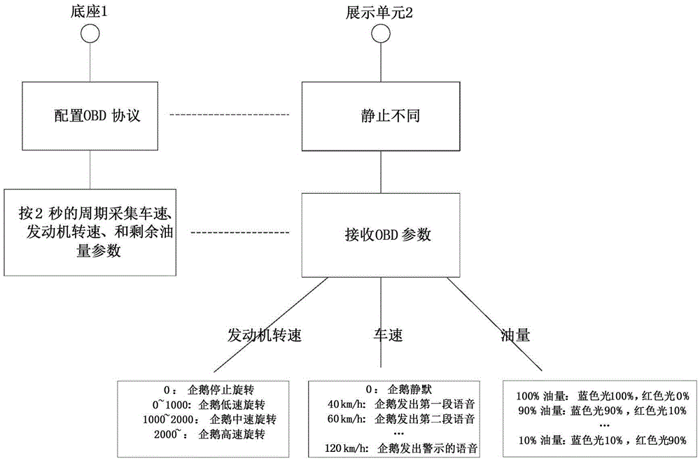
[0063] This embodiment provides a vehicle-mounted electronic device, which includes a base 1 and a display unit 2 electrically connected to the base 1 .
[0064] The base 1 is electrically connected to the vehicle OBD interface, and is used to obtain vehicle operation status data from the vehicle OBD interface, map the vehicle operation status data into corresponding control parameters, and transmit them to the display unit 2 .
[0065] The display unit 2 is configured to receive the control parameters, and perform corresponding dynamic display according to the control parameters.
[0066] The vehicle running state data includes relevant data such as engine speed, vehicle speed, fuel quantity, and exhaust emission.
[0067] Compared with the prior art, which only displays the vehicle running state data on the screen, this embodiment maps the vehicle running state data to corresponding control parameters for driving the display unit, so that the display effect of the display un...
Embodiment 2
[0076]On the basis of Embodiment 1, the vehicle-mounted electronic device described in this embodiment, as an optional implementation manner, the display module 22 further includes:
[0077] The motion control module 221 is configured to control the presentation unit 2 to perform corresponding action presentations according to the control parameters.
[0078] As an optional implementation manner, the display module 22 also includes:
[0079] The sound control module 222 is configured to control the display unit 2 to perform corresponding sound display according to the control parameters.
[0080] As an optional implementation manner, the display module 22 also includes:
[0081] The lighting control module 223 is configured to control the display unit 2 to perform corresponding lighting display according to the control parameters.
[0082] The display module described in this embodiment may include only one of the above display methods, or may include any combination of the ...
Embodiment 3
[0094] On the basis of Embodiment 1 or Embodiment 2, the vehicle-mounted electronic device described in this embodiment, the base 1 also includes a base interface 13, which is electrically connected to the first microcontroller 12, and the control parameter Transfer to the display unit 2.
[0095] The display unit 2 further includes a device interface 23 electrically connected to the second microcontroller 21 and transmitting the control parameters received from the base interface 13 to the second microcontroller 21 .
[0096] The base 1 and the display unit 2 are electrically connected through the base interface 13 and the device interface 23 .
[0097] In the vehicle-mounted electronic device described in this embodiment, as an optional implementation manner, the base interface 13 is a USB female connector, and the device interface 23 is a USB male connector.
[0098] The vehicle-mounted electronic device described in this embodiment is divided into two detachable independe...
PUM
 Abstract
Description
Claims
Application Information
 - R&D
- Intellectual Property
- Life Sciences
- Materials
- Tech Scout
- Unparalleled Data Quality
- Higher Quality Content
- 60% Fewer Hallucinations
Browse by: Latest US Patents, China's latest patents, Technical Efficacy Thesaurus, Application Domain, Technology Topic, Popular Technical Reports.
© 2025 PatSnap. All rights reserved.Legal|Privacy policy|Modern Slavery Act Transparency Statement|Sitemap|About US| Contact US: help@patsnap.com


