Spinning unit and spinner

A technology of spinning unit and spinning yarn, which is applied to spinning machine, open-end spinning machine, continuous winding spinning machine, etc. The effect of reducing the influence of static electricity

Active Publication Date: 2014-01-01
MURATA MASCH LTD
View PDF7 Cites 7 Cited by
  • Summary
  • Abstract
  • Description
  • Claims
  • Application Information

AI Technical Summary

Problems solved by technology

In this case, there is a possibility that the detection by the

Method used


Image

  • Spinning unit and spinner
  • Spinning unit and spinner
  • Spinning unit and spinner

Examples


Embodiment Construction

[0028] Hereinafter, embodiments of the present invention will be described with reference to the drawings. However, in the description of the drawings, the same reference numerals are attached to the same units, and their repeated descriptions are omitted.

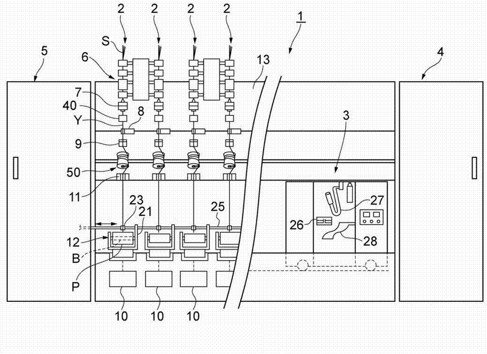
[0029] Such as figure 1 As shown, the air spinning machine 1 includes a plurality of spinning units 2 , a piecing cart 3 , a blower box 4 , and a prime mover box 5 . A plurality of spinning units 2 are arranged in a row, and each spinning unit 2 generates a spun yarn Y and winds it into a package P. The piecing cart 3 performs the piecing operation in the spinning unit 2 after cutting the spun yarn Y. Air supply sources and the like for generating suction airflow, swirling airflow, etc. in each part of the spinning unit 2 are accommodated in the blowing box 4 . The prime mover case 5 accommodates a prime mover and the like for supplying power to each part of the spinning unit 2 .

[0030] In addition, in the following ...


PUM


Abstract

The utility model provides a spinning unit and a spinner. The spinning unit is provided with a spinning device producing yarns, a yarn detecting part used for detecting the yarns and a discharging part used for releasing static from the yarns between the spinning device and the yarn detecting part. The spinner is provided with a plurality of spinning units.

Description

technical field [0001] The present invention relates to a spinning unit that generates a spun yarn and winds it into a package, and a spinning machine including a plurality of such spinning units. Background technique [0002] The spinning unit is equipped with: a spinning device that generates a spun yarn; a yarn storage device that stores the spun yarn by winding the spun yarn on a storage roller; and a winding device that winds the spun yarn into a package ( For example, refer to Japanese Patent Application Laid-Open No. 2011-99192). A yarn detection unit including a yarn clearer and the like is provided between the spinning device and the yarn storage device. [0003] In the spinning unit described in Japanese Patent Laid-Open No. 2011-99192, yarn guides are provided on the upstream side (spinning device side) and downstream side (yarn storage device side) of the yarn clearer. The yarn guide guides the textile yarn and restricts the yarn passage of the textile yarn to ...

Claims


Application Information

Patent Timeline
IPC IPC(8): D01H4/08D01H4/40
CPCD01H13/00D01H13/30
Inventor 冈正毅须佐见浩之
Owner MURATA MASCH LTD
Why Eureka
Try Eureka