Unlocking device for vehicle door in traffic field

A technology in the field of unlocking device and transportation, applied in the field of door system locking device, can solve the problems of high cost, poor reliability, complex mechanism, etc., and achieve the effect of obvious effect, simple structure and small unlocking force

Active Publication Date: 2015-06-17
NANJING KANGNI MECHANICAL & ELECTRICAL
View PDF8 Cites 1 Cited by
  • Summary
  • Abstract
  • Description
  • Claims
  • Application Information

AI Technical Summary

Problems solved by technology

This leads to the complexity of the whole mechanism, high cost and poor reliability

Method used


Image

  • Unlocking device for vehicle door in traffic field
  • Unlocking device for vehicle door in traffic field

Examples


Embodiment Construction

[0013] Below in conjunction with accompanying drawing, the present invention is further described in detail:

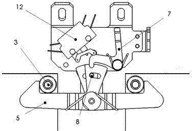
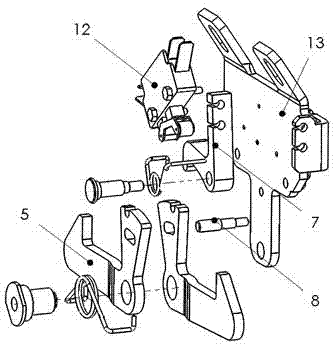
[0014] The present invention relates to an unlocking device for a vehicle door in the traffic field, comprising a locking hook 5, a roller 3, a locking plate 7 and a bottom plate 13, the roller 3 is arranged on the door leaf, the locking plate 7 and the locking hook 5 are arranged on the bottom plate 13 through a rotating shaft and Both of them can rotate freely on the base plate. On the locking plate 7, a protrusion is set. The locking hook 5 is L-shaped. One end is provided with a concave hole, and the other end is provided with a claw. Hold the roller 3 and the concave hole is embedded in the protrusion provided on the locking plate 7 to achieve a sufficient locking effect.

[0015] In the present invention, a torsion spring is arranged on the shaft of the locking plate 7 and the locking hook 5, so that the locking plate 7 and the locking hook 5 can return to their...


PUM


Abstract

The invention relates to an unlocking device for a vehicle door in a traffic field. The unlocking device consists of latch hooks and a locking plate, wherein the rotation or movement of the latch hooks is limited by meshing between the latch hooks and the locking plate; the blocking of a door leaf is released by the rotation or movement of the latch hooks, so that the locking or unlocking of a door system is realized. The unlocking device for the vehicle door in the traffic field has the advantages that the structure is simple, the releasing force is small, and the manufacturing cost is low.

Description

technical field [0001] The invention relates to an unlocking device for a single or double door of a vehicle in the traffic field, and belongs to the technical field of door system locking devices. Background technique [0002] At present, the door system using the drive mechanism driven by the main shaft has always had the problem of locking and unlocking. Various brakes, or locks driven by electromagnetic, hydraulic, or pneumatic methods are commonly used to lock and unlock the door system. The unlocking often requires additional power source. This leads to the complexity of the whole mechanism, high cost and poor reliability. [0003] At present, there are some passive locking devices in the technology. When unlocking, the main shaft is basically rotated. Because the driving shaft is connected with the motor, it needs to overcome a relatively large force when rotating. Contents of the invention [0004] Purpose of the invention: The purpose of the invention is to prov...

Claims


Application Information

Patent Timeline
Patent Type & Authority Patents(China)
IPC IPC(8): E05B77/00E05B63/14
Inventor 曾世文张晓娟王维
Owner NANJING KANGNI MECHANICAL & ELECTRICAL
Why Eureka
Try Eureka