Piezoelectric type brake executing mechanism of electronic mechanical brake system of vehicle

An electromechanical braking and actuator technology, applied in the direction of brake actuators, mechanical equipment, gear transmission mechanisms, etc., can solve the problems of complex structure of electromechanical brake actuators and affect the working performance of EMB system, and improve dynamic performance. Response performance and braking performance, high dynamic response performance, and simple structure

Active Publication Date: 2014-01-01
HAIAN LIANKE AUTOMOBILE PARTS +1
View PDF9 Cites 15 Cited by
  • Summary
  • Abstract
  • Description
  • Claims
  • Application Information

AI Technical Summary

Problems solved by technology

The structure of the motor-type brake actuator is relatively complex, and because the drive motor works in a "stall" environment, it affects the working performance of the EMB system

Method used


Image

  • Piezoelectric type brake executing mechanism of electronic mechanical brake system of vehicle
  • Piezoelectric type brake executing mechanism of electronic mechanical brake system of vehicle

Examples


Embodiment 1

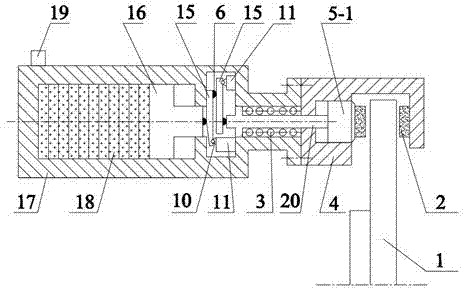
[0018] Such as figure 1 As shown, a piezoelectric brake actuator of a vehicle electromechanical brake system includes a brake caliper body 4, a housing 17, a piston 16, a brake piston assembly 5, a return spring 3, a displacement amplification mechanism, a piezoelectric The element 18 and the friction block 2 respectively located on both sides of the brake disc 1 of the vehicle and cooperating with the brake disc 1 for braking, the brake piston assembly 5 is slidably installed on the brake caliper body 4, the piston 16 and the piezoelectric element 18 is located in the housing 17, one side of the piston 16 is in contact with the piezoelectric element 18, and the displacement amplification mechanism is arranged between the other side of the piston 16 and the brake piston assembly 5 so that when the piezoelectric element 18 applies an external electric field to generate When the mechanical deformation in the axial direction of the piston 16 forms an axial displacement in this di...

Embodiment 2

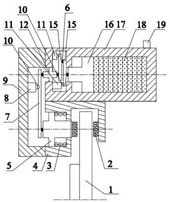
[0028] Such as figure 2 As shown, a piezoelectric brake actuator of a vehicle electromechanical brake system includes a brake caliper body 4, a housing 17, a piston 16, a brake piston assembly 5, a return spring 3, a displacement amplification mechanism, a piezoelectric The element 18 and the friction block 2 respectively located on both sides of the brake disc 1 of the vehicle and cooperating with the brake disc 1 for braking, the brake piston assembly 5 is slidably installed on the brake caliper body 4, the piston 16 and the piezoelectric element 18 is located in the housing 17, one side of the piston 16 abuts against the piezoelectric element 18, and the displacement amplifying mechanism is arranged between the other side of the piston 16 and the brake piston assembly 5 so that when the piezoelectric element 18 is applied external The electric field produces mechanical deformation in the axial direction of the piston 16 to form an axial displacement in this direction. When...


PUM


Abstract

The invention discloses a piezoelectric type brake executing mechanism of an electronic mechanical brake system of a vehicle. The piezoelectric type brake executing mechanism comprises a brake caliper body, a shell, a piston, a brake piston component, a return spring, a displacement amplifying mechanism, a piezoelectric element and a friction block. The brake piston component is installed on the brake caliper body in a sliding mode, the piston and the piezoelectric element are arranged in the shell, one side of the piston abuts against the piezoelectric element, the displacement amplifying mechanism is arranged between the other side of the piston and the brake piston component, one end of the return spring abuts against the brake caliper body, and the other end of the return spring abuts against the brake piston component. The displacement amplifying mechanism comprises a displacement amplifying lever, a protrusion point, a fixed hinge, a base and the like, on the basis of the lever principle, the small displacement amount of the piezoelectric element is amplified, and the requirement of the friction block for the movable displacement is met. An electric field value exerted by the piezoelectric element is adjusted to achieve the control over brake force of wheels, and the dynamic response performance and the brake performance of the brake system can be improved.

Description

technical field [0001] The invention relates to a piezoelectric braking actuator of a vehicle electromechanical braking system, belonging to the technical field of vehicle braking. Background technique [0002] The braking system is one of the important components of the car, which is directly related to the comprehensive performance of the car and the safety of life and property, including service brakes, parking brakes and auxiliary brakes. The service brake is the main brake of the car, and generally adopts drum or disc friction braking method, which converts the kinetic energy and potential energy of the car into heat energy through friction, so as to realize the purpose of deceleration or braking of the car. Although the traditional hydraulic and pneumatic service brakes can meet the requirements of the existing braking regulations, they have shortcomings such as slow response speed, non-active adjustment, and difficult integrated control, which are not suitable for...

Claims


Application Information

Patent Timeline
Patent Type & Authority Applications(China)
IPC IPC(8): F16D65/14F16D121/18
Inventor 王奎洋何仁唐金花胡淳
Owner HAIAN LIANKE AUTOMOBILE PARTS
Why Eureka
Try Eureka