Commercial oven hearth

A technology for commercial stoves and hearths, applied in household stoves, household stoves/stoves, applications, etc., can solve the problems of not meeting aesthetic requirements, poor surface finish, low heat utilization rate, etc., to achieve improved appearance, aesthetics, The effect of improving the utilization rate of heat energy

Active Publication Date: 2014-01-01
HUBEI ZHONGRUITIANHENG ENERGY SAVING TECH DEV
View PDF10 Cites 5 Cited by
  • Summary
  • Abstract
  • Description
  • Claims
  • Application Information

AI Technical Summary

Problems solved by technology

[0003] The disadvantage of the material is that the heat reflection is poor, which makes the heat energy utilization rate low; at the same time, a lot of heat is lost through the furnace wall material; in addition, these ma

Method used


Image

  • Commercial oven hearth
  • Commercial oven hearth
  • Commercial oven hearth

Examples


Example Embodiment

[0022] Example one

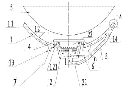
[0023] Contrast figure 1 , The furnace of the commercial stove of the present invention includes a furnace wall 1, a burner 2 and a hot air pipe 3. The burner 3 is placed in the center of the bottom of the furnace wall 1. The furnace wall 1 is a hollow wall formed by an outer wall 12 and an inner wall 11 made of glass-ceramics; the outer wall 11 is provided with an air inlet 13 and an air outlet 14, hot air The pipe 3 connects the air outlet 14 and the air inlet 21 at the lower end of the burner, and guides the hot air gas discharged from the air outlet 12 to the burner 2.

[0024] The inner wall 12 made of crystallized glass is in the shape of a pot, and the bottom is provided with a burner hole 121 through which the burner passes. The outer wall 11 is a ferrule adapted to the shape of the inner wall, and is sleeved on the outside of the inner wall 12. The outer wall 11 can be made of metal or ceramic material, and the metal material is generally a thin...

Example Embodiment

[0028] Example two

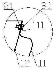
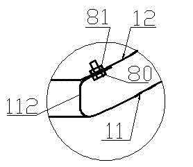
[0029] The furnace of the commercial stove of the present invention can also be designed as Figure 4 The structure includes the furnace wall 1 and the burner 2, the hot air pipe 3 and the heat-absorbing air pipe 9 placed in the center of the furnace bottom. The furnace wall 1 is made of glass-ceramic, and the heat-absorbing air pipe is tightly wound along the outside of the furnace. On the furnace wall 1, the air outlet 82 of the heat absorption air pipe 4 is connected to the air inlet at the lower end of the burner through the hot air pipe 3, and the heated air in the heat absorption air pipe is introduced to the burner.

[0030] Further, the heat absorption air duct 9 is made of a material with good thermal conductivity, such as stainless steel. The heat-absorbing air pipe 9 is tightly spirally wound on the furnace wall 1, and its air inlet end 91 and air outlet end 92 are respectively arranged at the bottom and upper part of the opposite furnace wall. The...


PUM


Abstract

The invention relates to a commercial oven hearth. The commercial oven hearth comprises a hearth wall and a combustor placed in the center of the bottom of the heart, and is characterized by also comprising a hot air pipe, wherein the hearth wall is a hollow wall formed by an outer wall and an inner wall made of microcrystalline glass; a gas inlet and a gas outlet are formed in the outer wall; and the hot air pipe is connected with the gas outlet and an air inlet at the lower end of the combustor, and is used for leading the gas preheated by the hollow wall into the combustor. The commercial oven hearth has the benefits that room-temperature gas entering the hollow wall is preheated by high-temperature heat diffused by the inner wall of the hearth and then enters the combustor to participate in combustion, so that the heat efficiency is improved; the air-cooled energy can guarantee that the microcrystalline glass can adapt to naked flame combustion; the smooth finish of the inner wall made of the microcrystalline glass is greatly improved, so that cleaning is facilitated, less heat energy can be absorbed, more heat energy can be reflected, and the heat efficiency is improved; the attractiveness of an oven is improved; and processing and assembling efficiency is higher.

Description

technical field [0001] The invention relates to kitchen and sanitary equipment, in particular to a commercial stove hearth. Background technique [0002] When the furnace of a commercial stove is working, the temperature in the furnace generally reaches 800~1200°C, and the high-temperature flame will impact the furnace wall. Therefore, the inner wall material of the current commercial stove is generally refractory bricks, refractory mud or metal materials. These furnace walls [0003] The disadvantage of the material is that the heat reflection is poor, which makes the heat energy utilization rate low; at the same time, a lot of heat is lost through the furnace wall material; in addition, these materials are easily damaged, and the surface finish is poor. Once the cooked food falls into the furnace, it is not easy to clean; the appearance is not beautiful , Does not meet the aesthetic requirements of modern kitchens. Contents of the invention [0004] The purpose of the...

Claims


Application Information

Patent Timeline
IPC IPC(8): F24C15/00F24C3/08
Inventor 张跃虎金毅
Owner HUBEI ZHONGRUITIANHENG ENERGY SAVING TECH DEV
Why Eureka
Try Eureka