
Feed source position compensation method of large-scale deformed single reflection surface antenna

A compensation method and single-reflection technology, applied in antennas, special data processing applications, instruments, etc., can solve problems such as cumbersome mathematical expressions, difficult effective applications, and high compensation calculation costs

Inactive Publication Date: 2014-01-01
XIDIAN UNIV
View PDF3 Cites 15 Cited by
  • Summary
  • Abstract
  • Description
  • Claims
  • Application Information

AI Technical Summary

Problems solved by technology

However, most researchers analyze the deformation of deformed single-reflector antennas, and the mathematical expressions obtained are not only cumbersome and complicated to solve, but also cannot reflect the real deformation of the reflector. High cost, difficult to effectively apply

Method used


Image

  • Feed source position compensation method of large-scale deformed single reflection surface antenna
  • Feed source position compensation method of large-scale deformed single reflection surface antenna
  • Feed source position compensation method of large-scale deformed single reflection surface antenna

Examples


Embodiment Construction

[0044] The present invention will be described in further detail below with reference to the accompanying drawings.

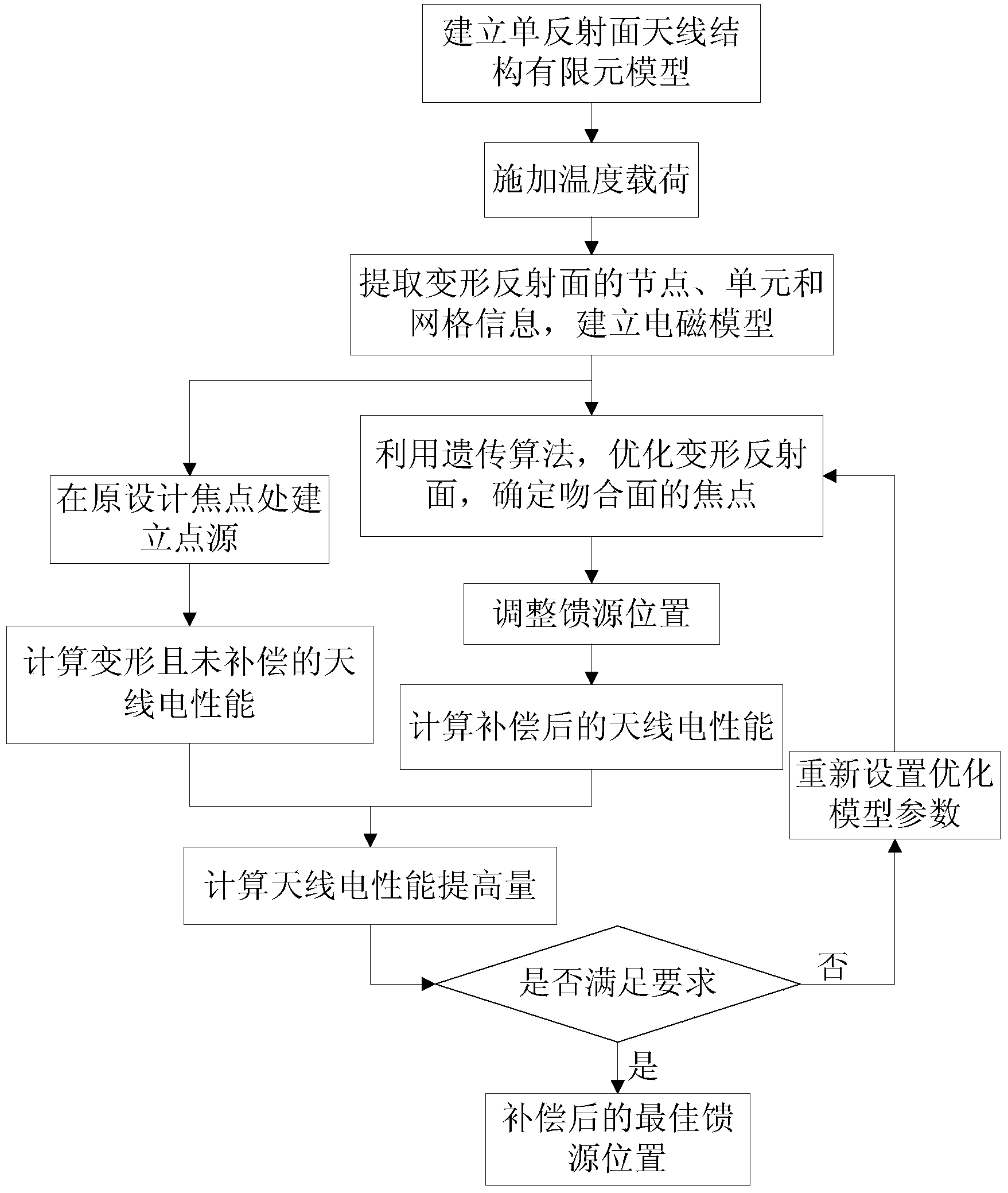
[0045] The present invention is a kind of feed position compensation method of deformed large-scale single-reflector antenna, and the steps of the method are as follows: figure 1 Shown:

[0046] Step 1 Establish the finite element model of the undeformed single reflector antenna in ANSYS

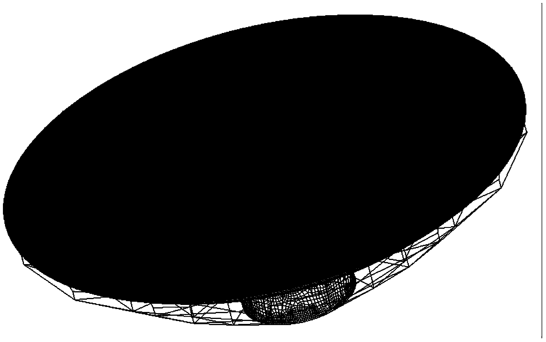
[0047] According to the structural parameters, operating frequency and material properties of the undeformed single-reflector antenna, the finite element model of the undeformed single-reflector antenna is established in ANSYS, where the structural parameters include the aperture and focal length; the material properties include the material of the single-reflector antenna back frame and the density, thermal conductivity, specific heat, Poisson's ratio, elastic modulus, and thermal expansion coefficient of the single-dish antenna panel. figure 2 It is the finite element mode...


PUM


Abstract

The invention discloses a feed source position compensation method of a large-scale deformed single reflection surface antenna, which mainly solves the problem that the electric performance of a single reflection surface antenna is lowered due to thermal deformation. The method adopts the scheme of 1, establishing a finite element model of an undeformed single reflection surface antenna according to the structure parameter of the antenna; 2, calculating node coordinates when deformation occurs after a temperature load is loaded on the undeformed single reflection surface antenna; 3, extracting the node coordinates and unit information of a deformed main reflection surface, and establishing an electromagnetic model of the thermal deformed main reflection surface of the antenna; 4, calculating the electric performance before the antenna is compensated in the electromagnetic model of the thermal deformed main reflection surface of the antenna; 5, optimizing deformation parameters of the deformed main reflection surface by means of a genetic algorithm, obtaining the position and the direction of a feed source from the deformation parameters, and calculating the electric performance after the antenna is compensated; 6, comparing the electric performance of the antenna before and after compensation to judge whether the improvement of the electric performance meets the requirement, if so, judging the position to be the optimum position of the feed source, and if not, setting and optimizing the parameters again and calculating until the requirement is met.

Description

technical field [0001] The invention belongs to the technical field of antennas, in particular to a compensation method for a deformed large-scale single-reflector antenna, which is used to guide the adjustment of the feed source position of the deformed large-scale single-reflector antenna so that its electrical performance can be optimized. Background technique [0002] As large-aperture, high-frequency reflector antennas are increasingly widely used in communication and space exploration, the relationship between antenna structure and electromagnetic performance is getting closer. The small deformation of the reflective surface caused by such effects will also have a serious impact on the electrical performance of the high-frequency antenna. In the past, the root mean square error of the processed reflective surface surface was calculated from the acceptable electrical performance loss index through the Ruze formula. With the increase of the operating frequency, it is mor...

Claims


Application Information

Patent Timeline
IPC IPC(8): G06F17/50H01Q19/10
Inventor 王从思李辉李兆刘鑫王伟朱敏波陈光达段宝岩黄进保宏宋立伟李鹏李娜李江江
Owner XIDIAN UNIV
Learn More