

Visualized intelligent bus stop board
A technology of intelligent bus and stop signs, which is applied to the arrangement of variable traffic instructions, traffic control system, traffic control system of road vehicles, etc. It can solve the problems of not being able to notify in time, not being able to clearly see the running time of bus routes, and delaying travel time, etc. question
- Summary
- Abstract
- Description
- Claims
- Application Information
AI Technical Summary
Problems solved by technology
Method used
Image

Examples
Embodiment 1
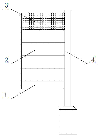
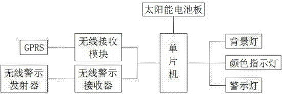
[0028] refer to figure 1 and figure 2 , the visualized intelligent bus stop sign of the present embodiment includes a sign 1 and a support column 4 for fixing the sign 1, the sign 1 is divided into a plurality of indication areas 2, and also includes a single-disk computer and a power supply for the single-chip microcomputer, the power supply It is a solar battery panel 3 arranged on the surface of the sign 1 . Each indicator area 2 of the signboard 1 is respectively provided with a background light and a color indicator light. The luminous line of the background light is white light, and the luminous line of the color indicator light is green light. The background light and the color indicator light are connected with the single-chip microcomputer respectively. Connect wireless receiving module, be provided with the GPRS that communicates with wireless receiving module on the bus corresponding to the bus number indicated by each indicator area 2, when the bus of a certain r...
Embodiment 2
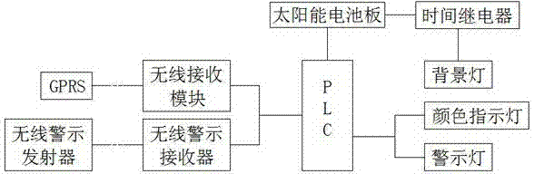
[0031] refer to figure 1 and image 3, the visualized intelligent bus stop sign of the present embodiment includes a sign 1 and a support column 4 of a fixed sign 1, the sign 1 is divided into a plurality of indication areas 2, and also includes a PLC and a power supply for the PLC, and the power supply is set The solar panel 3 on the surface of the sign 1 . Each indicator area 2 of the sign 1 is equipped with a background light, and each indicator area 2 of the sign 1 is equipped with a color indicator light connected to the PLC respectively. The glow line is green light. The PLC is connected to the wireless receiving module, and the bus corresponding to the bus number indicated by each indicator area 2 is provided with a GPRS for communicating with the wireless receiving module. Each indicator area 2 is provided with a time relay connected in series with the background light, and the lighting time of the background light is controlled by the time relay. The time relay ca...
Embodiment 3
[0034] refer to figure 1 and Figure 4 The difference between this embodiment and the first embodiment is that the wireless transmitter set on the bus corresponding to the bus number indicated by each indicating area 2 is a wireless transmitting module, and each indicating area 2 is provided with a background The time relay connected in series with the lights cuts off or connects the power supply line of the background light through the time relay, and then controls the lighting time of the background light, thereby reminding the waiting passengers which bus has stopped running or has not yet run, and which bus is running .
PUM
 Abstract
Description
Claims
Application Information