
Artificial lung

An artificial lung, hollow technology, applied in the field of artificial lung, can solve the problems of reducing gas exchange performance, reducing blood filling volume, etc.

Active Publication Date: 2014-01-01
TERUMO KK
View PDF4 Cites 13 Cited by
  • Summary
  • Abstract
  • Description
  • Claims
  • Application Information

AI Technical Summary

Problems solved by technology

[0005] However, in conventional artificial lungs, it is impossible to reduce the blood filling volume without degrading the gas exchange performance and increasing the pressure loss during blood flow.

Method used


Image

  • Artificial lung
  • Artificial lung
  • Artificial lung

Examples


no. 1 Embodiment approach

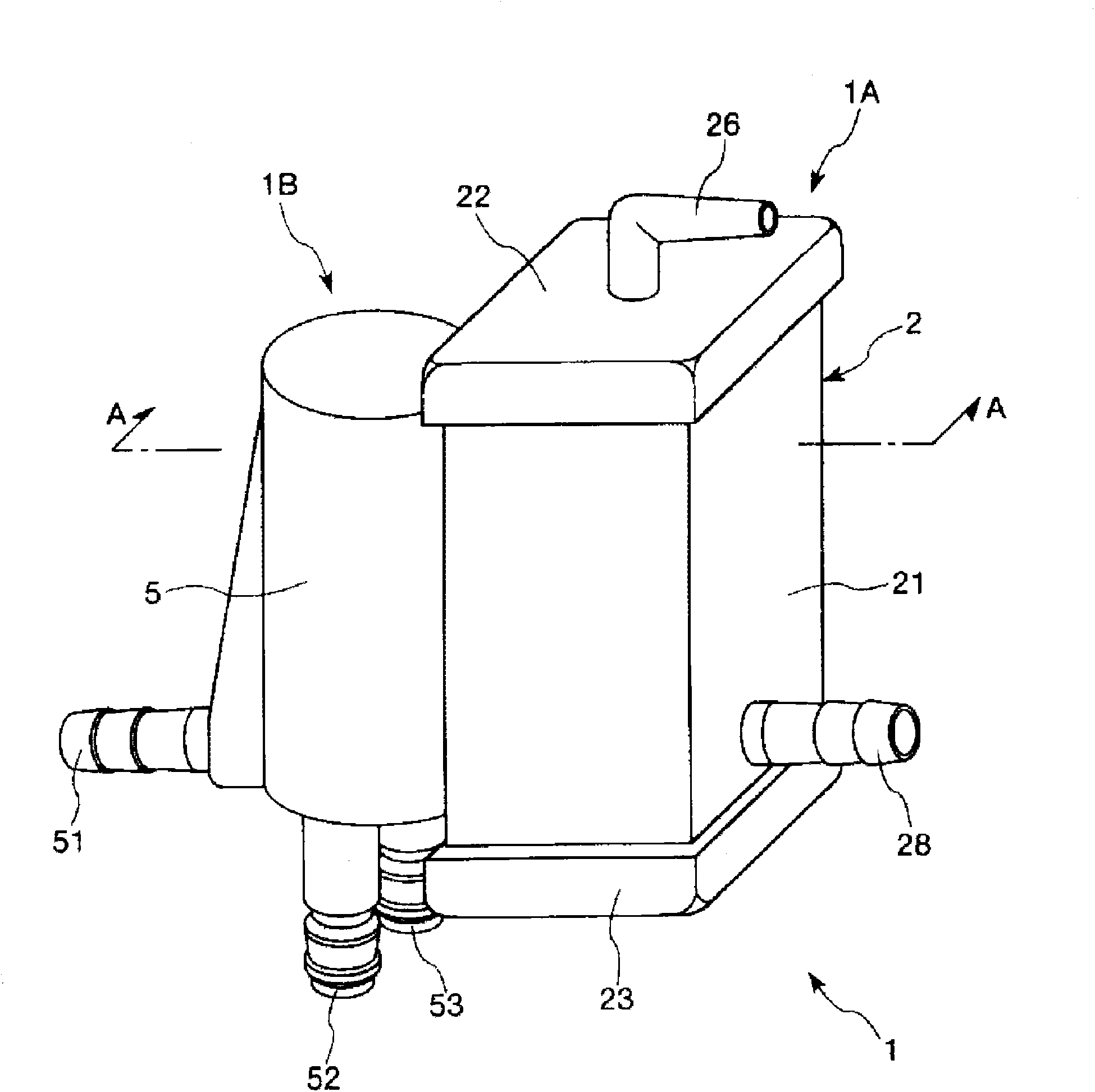
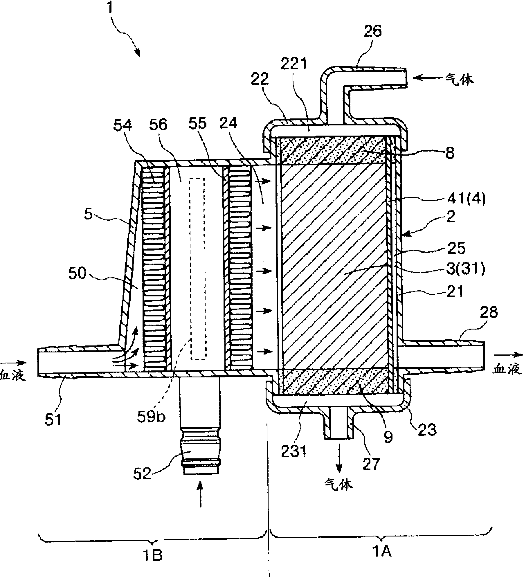
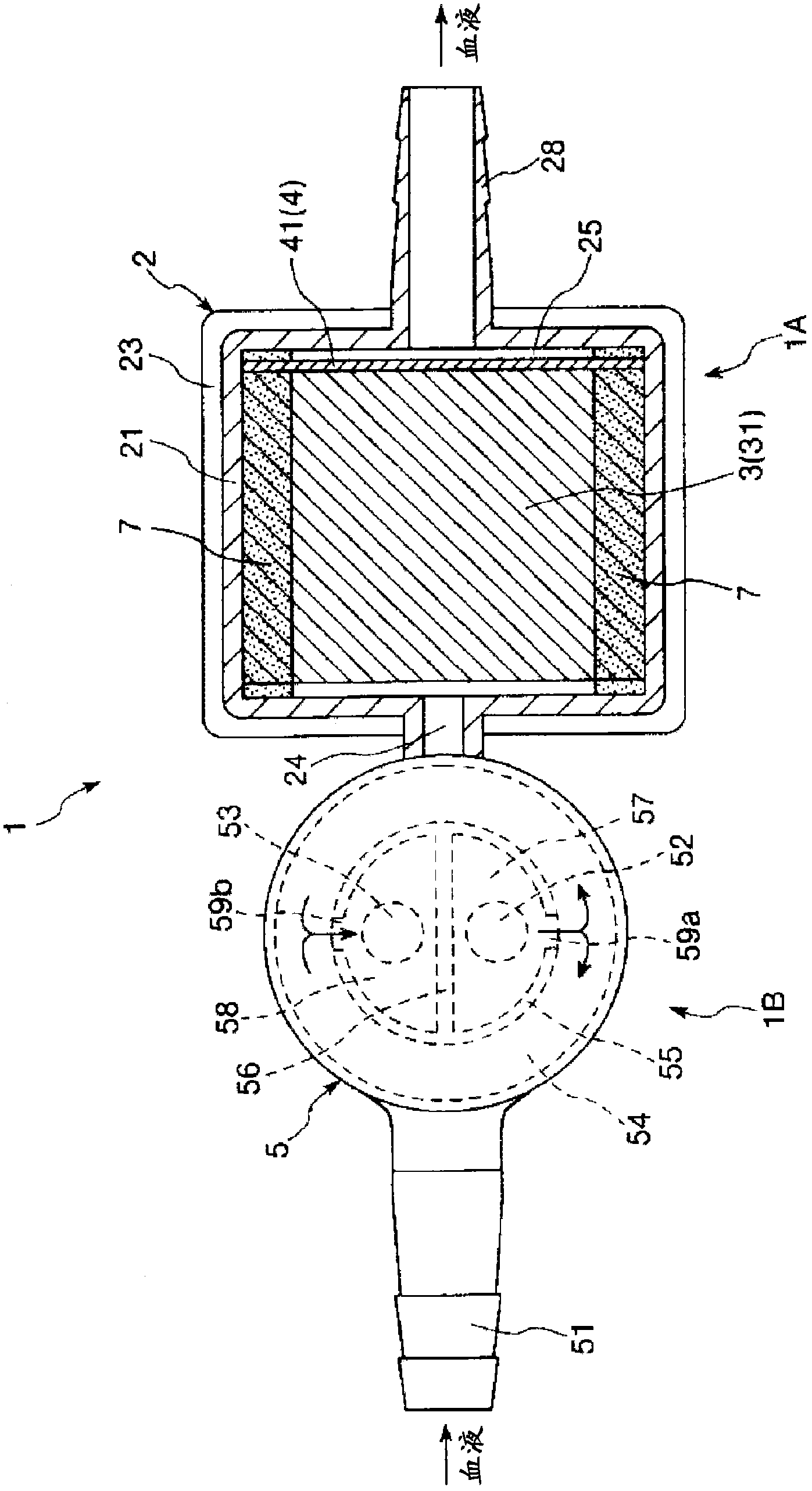
[0038] figure 1 It is a perspective view showing the first embodiment of the artificial lung of the present invention, figure 2 for figure 1 A-A line sectional view in, image 3 for figure 1 A cross-sectional view of the artificial lung in the shown artificial lung, Figure 4 for figure 2 The enlarged cross-sectional view of the lower right part (hollow fiber membrane layer and filter element) in . Figure 5 for schematic representation figure 1 Perspective view of the hollow fiber membrane layer and septum of the artificial lung shown. Figure 6 to represent figure 1 Perspective view of the hollow fiber membrane shown. It should be noted that the figure 1 and figure 2 The upper side is referred to as "upper" or "upper", the lower side is referred to as "lower" or "below", the left side is referred to as "blood inflow side" or "upstream side", and the right side is referred to as "blood outflow side" or "downstream side". "Be explained.

[0039] Figure 1 to Fi...

no. 2 Embodiment approach

[0120] Figure 7 It is a plan view showing a second embodiment of the artificial lung of the present invention, Figure 8 For viewing from the arrow B side Figure 7 The diagram of the artificial lung shown, Figure 9 for Figure 6 The C-C line sectional view in, Figure 10 for from Figure 8 In the diagram observed on the arrow D side, Figure 11 for Figure 7 E-E line sectional view in, Figure 11 for Figure 7 The F-F line sectional view in . It should be noted that the Figure 7 , Figure 9 and Figure 10 The left side in is called "left" or "left", and the right side is called "right" or "right". in addition, Figure 7 ~ Figure 12 In the description, the inner side of the artificial lung is referred to as the "blood inflow side" or "upstream side", and the outer side is referred to as the "blood outflow side" or "downstream side".

[0121] Hereinafter, a second embodiment of the artificial lung of the present invention will be described with reference to the...

Embodiment 1

[0169] manufacture Figure 7 ~ Figure 12 The artificial lung shown. As a constituent material of each hollow fiber membrane of the hollow fiber membrane layer, polypropylene is used. In addition, the dimensions of the hollow fiber membranes are as follows.

[0170] Average spacing distance ε: 60μm

[0171] Outer diameter OD: 200μm

[0172] OD / ε: 3.3

[0173] Inner diameter ID: 140μm

[0174] Effective length L: 170mm


PUM

PropertyMeasurementUnit
porosityaaaaaaaaaa
aperture sizeaaaaaaaaaa

Abstract

An oxygenator includes: a housing; a hollow fiber membrane layer that is stored in the housing and has multiple integrated hollow fiber membranes 31 with a gas exchange function; a gas inlet portion and a gas outlet portion that are provided on the upstream and downstream of gas passages in lumens of the hollow fiber membranes 31, respectively; and a blood inlet portion and a blood outlet portion that are provided on the upstream and downstream of blood passages outsides of the hollow fiber membranes 31, respectively. The hollow fiber membranes 31 in the hollow fiber membrane layer are fixed to each other at one end portions and the other end portions thereof. Conditions 30 ‰¤ µ ‰¤ 60 and OD ‰¤ 4.5 × µ are met where µ [µm] is an average separation distance between the adjacent hollow fiber membranes 31 at a fixed portion of the hollow fiber membrane layer and OD [µm] is the outer diameter of the hollow fiber membranes 31,.

Description

technical field [0001] The present invention relates to artificial lungs (oxygenators). Background technique [0002] Conventionally, as an artificial lung, a structure in which gas exchange is performed using a hollow fiber membrane layer in which a plurality of hollow fiber membranes are laminated is known (for example, refer to Patent Document 1). [0003] The artificial lung described in Patent Document 1 has a housing, a hollow fiber membrane layer housed in the housing and having a cylindrical overall shape, a blood inflow port, a blood outflow port, a gas inflow port, and a gas inflow port. Gas exchange between blood and gas, ie oxygenation, decarbonation of gases. [0004] In addition, in artificial lungs, in order to reduce the amount of blood circulating outside the body, it is required to reduce the filling amount of blood. [0005] However, in conventional artificial lungs, it is impossible to reduce the blood filling amount without reducing the gas exchange pe...

Claims


Application Information

Patent Timeline
Patent Type & Authority Applications(China)
IPC IPC(8): A61M1/18B01D63/02B01D71/26A61M1/36
CPCB01D63/026B01D71/26A61M1/1698B01D63/02A61M1/3623B01D71/261B01D71/262B01D69/081
Inventor 竹内和彦
Owner TERUMO KK
Learn More