Wireless communication system and wireless slave and master units used therein

A wireless communication system and wireless communication technology, applied in the field of wireless handsets and wireless masters, can solve problems such as easy jitter, delay, and reduced timing accuracy

Inactive Publication Date: 2014-01-01
PANASONIC INTELLECTUAL PROPERTY MANAGEMENT CO LTD
View PDF10 Cites 6 Cited by
  • Summary
  • Abstract
  • Description
  • Claims
  • Application Information

AI Technical Summary

Problems solved by technology

[0011] However, the signal sent from the wireless master unit is prone to jitter due to the influence of the transmission environment, and the timing to reach the wireless slave unit may be delayed from the regular timing.
In the wireless handset as described in Patent Document 1, since the timing error is corrected using the reception timing of the signal, it is difficult to perform high-precision correction, resulting in reduced timing accuracy.

Method used


Image

  • Wireless communication system and wireless slave and master units used therein
  • Wireless communication system and wireless slave and master units used therein
  • Wireless communication system and wireless slave and master units used therein

Examples


no. 1 approach

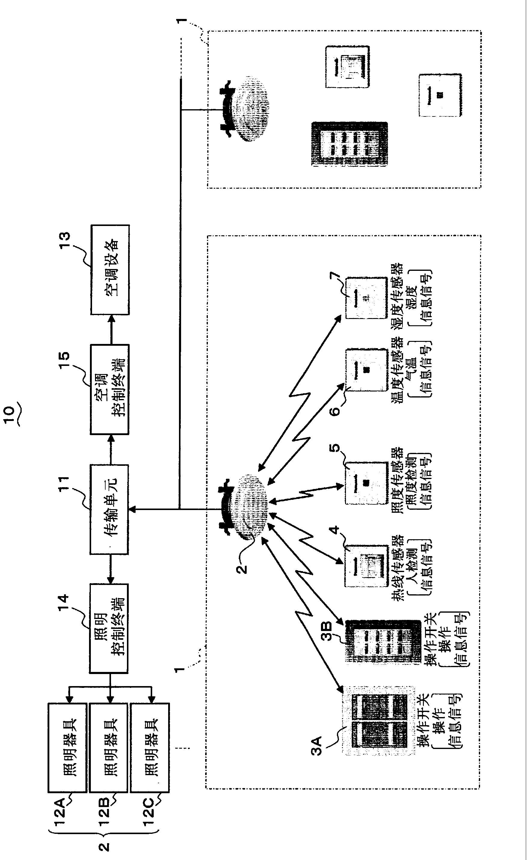
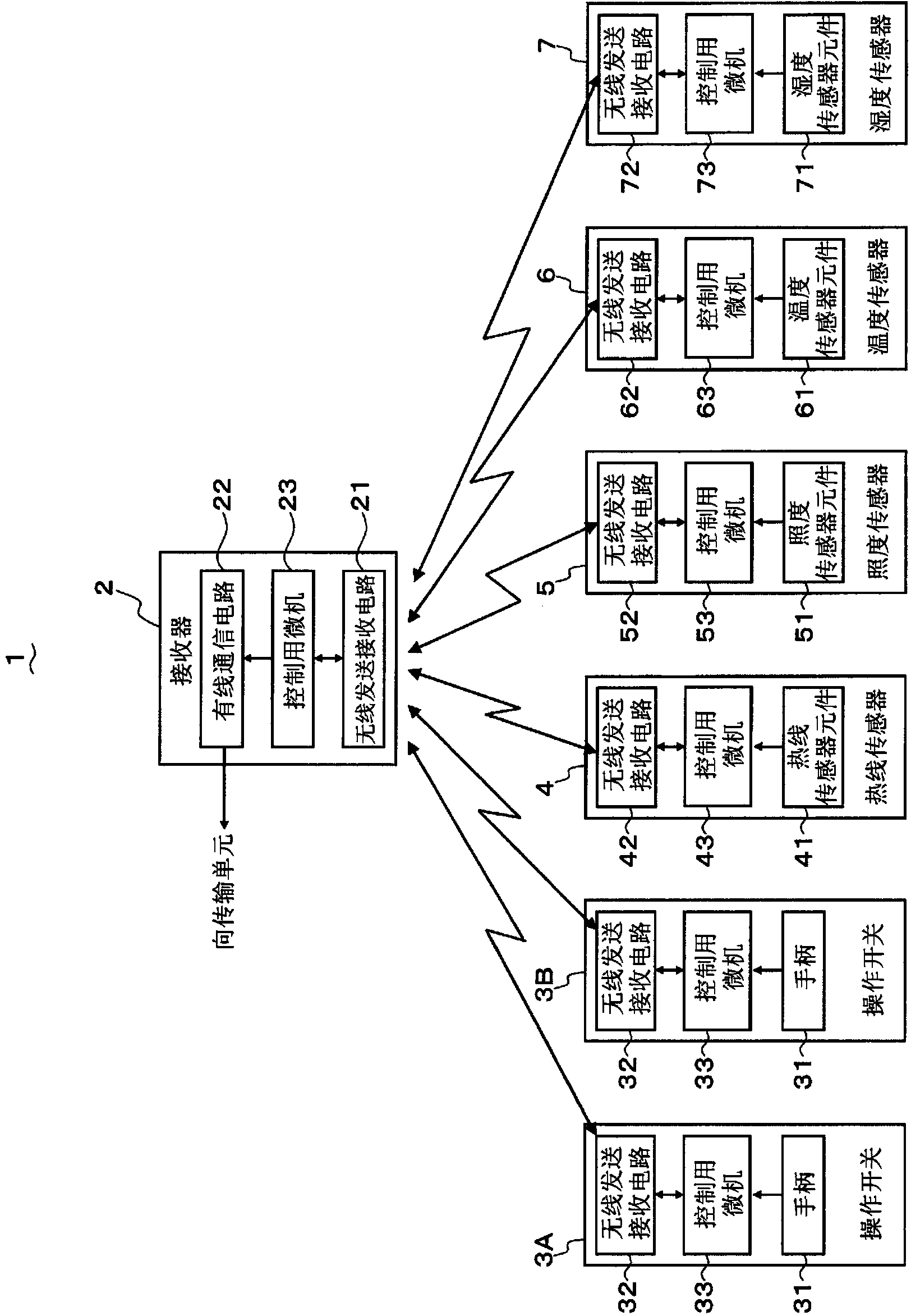
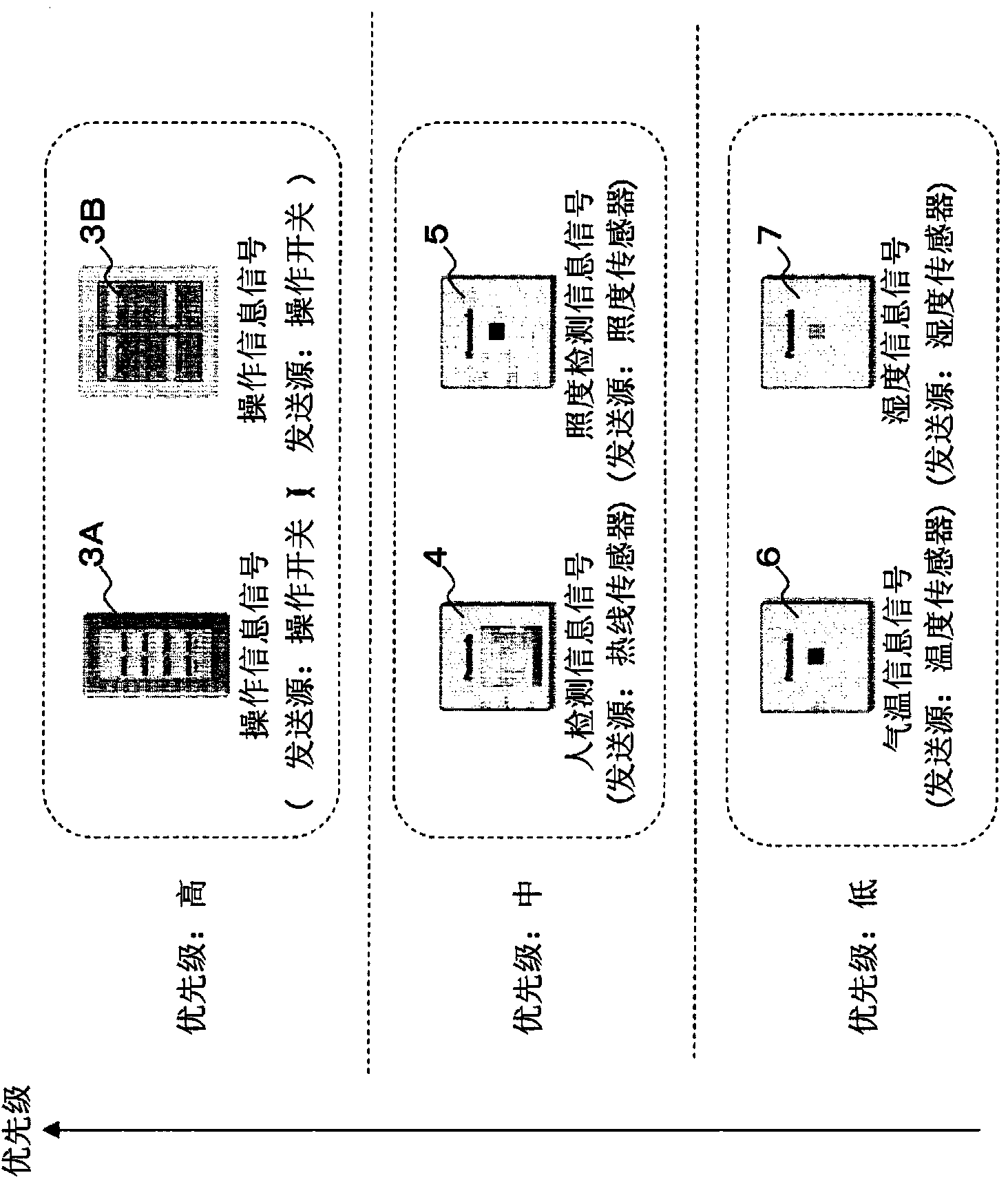
[0057] figure 1 The configuration of the device control system including the wireless communication system according to the first embodiment of the present invention is shown. The wireless communication system 1 includes a wireless receiver (hereinafter referred to as a receiver) 2 as a wireless master and a plurality of wireless slaves that wirelessly transmit various information signals to the receiver 2 . These wireless handsets include operation switches 3A, 3B, heating sensor 4, illuminance sensor 5, temperature sensor 6, and humidity sensor 7 (hereinafter collectively referred to as operation switch 3A, etc.). The number of operation switches is not limited to that shown in the figure, and there may be one or a plurality of them.

[0058] The device control system 10 includes a wireless communication system 1 (receiver 2, operation switch 3A, etc.), a transmission unit 11, lighting fixtures 12A, 12B... (hereinafter collectively referred to as lighting fixtures 12A, etc...

no. 2 approach

[0145] Next, a device control system including a wireless communication system according to a second embodiment of the present invention will be described with reference to the drawings. The structure of the equipment control system and figure 1 The structure shown is the same, so again refer to figure 1 to explain its structure. In addition, in the drawings of the second embodiment, the same symbols are attached to the same configurations as those of the above-mentioned first embodiment.

[0146] Figure 15 The configuration of the wireless communication system 1 according to the present embodiment is shown. In the present embodiment, the wireless communication system 1 includes an operation switch 3 having a configuration equivalent to that of the operation switches 3A, 3B of the first embodiment described above. However, the number of operation switches is not limited. Moreover, the wireless communication system 1 is provided with the temperature-humidity sensor 8 wh...


PUM


Abstract

A wireless communication system wherein the higher the priority level of an information signal to be transmitted by a slave unit, such as an operating switch, is, the shorter the time period (t1) of a carrier sense to be performed before the transmission of the information signal is caused to be. In this way, even when slave units are about to transmit information signals of mutually different priority levels by use of the same time slot, one of the slave units being about to transmit an information signal having the higher priority level than any other slave unit is allowed to cause the time period (t1) of a carrier sense, which is to be performed before the transmission of the information signal, to be shorter than any other slave unit, so that the one slave unit can transmit the information signal earliest. Thus, the slave unit that becomes able to transmit the information signal earliest is caused to transmit the information signal, thereby allowing the information signal having the highest priority level to be transmitted earliest, while causing each of the other units to detect that transmission by use of the carrier sense, thereby causing the other unit to defer the transmission of the information signal.

Description

technical field [0001] The present invention relates to a wireless communication system that transmits information signals from a wireless slave unit to a wireless master unit using radio waves, and a wireless slave unit and a wireless master unit used in the wireless communication system. Background technique [0002] Conventionally, a radio communication system is known in which a plurality of radio slave units transmit various information signals to a radio master unit in a slotted ALOHA (Slotted ALOHA) manner using a carrier of the same frequency. In this wireless communication system, a wireless slave unit transmits an information signal in an arbitrary time slot in synchronization with time slots obtained by dividing time at fixed intervals. When the wireless handset transmits information signals, in order to avoid interference between its own radio waves and radio waves from other radios, it performs carrier sense to check whether radio waves are sent from other radio...

Claims


Application Information

Patent Timeline
Patent Type & Authority Applications(China)
IPC IPC(8): H04W74/08H04Q9/00H04W4/04
CPCH04W48/00H04W52/0216H04L1/1854H04W74/0808H04Q2209/826H04Q9/00H04W84/20H04W52/0219H04W56/001H04L5/003Y02D30/70H04L12/407
Inventor 长田雅裕
Owner PANASONIC INTELLECTUAL PROPERTY MANAGEMENT CO LTD
Why Eureka
Try Eureka