

Synchronizing device of drawer sliding rails
A technology of synchronizing device and sliding rail, which is applied to drawers, furniture parts, household appliances, etc., can solve the problems of difficult installation and positioning, complex structure, etc., and achieve smooth opening and closing process, high connection compactness, and uniform force. Effect
- Summary
- Abstract
- Description
- Claims
- Application Information
AI Technical Summary
Problems solved by technology
Method used
Image

Examples
no. 1 example
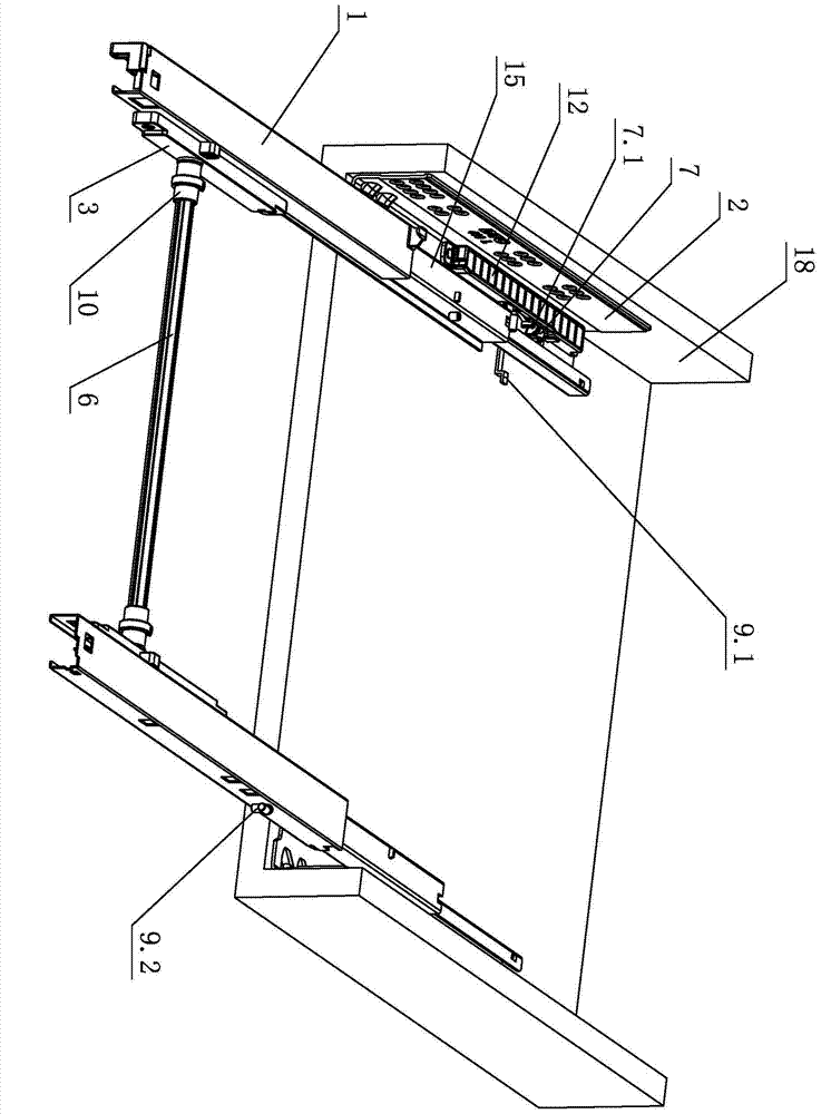
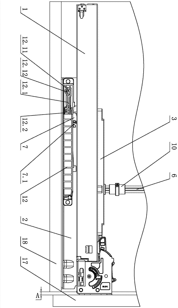
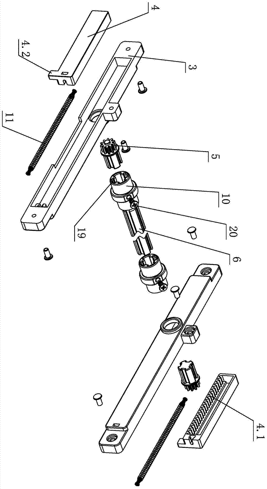
[0024] see figure 1 - Figure 6 , the synchronous device of this drawer slide rail comprises two sets of slide rail assemblies arranged on the left and right cabinet side panels 18, the slide rail assembly is provided with a drawer, and the drawer is at least made up of bottom and front panel 17. The slide rail assembly is composed of a moving slide rail 1, a middle slide rail 15 and a fixed slide rail 2, and the three are slidingly connected by rolling elements. Among them, the left and right moving slide rails 1 or the fixed slide rails 2 are provided with a synchronizing device for drawers, the synchronizing device at least includes a chute seat 3 and a sliding block 4, and the sliding block 4 acts on the chute seat 3 and is set on it. There is a rack 4.1, and the chute seat 3 corresponds to the rack 4.1 to rotate and is provided with a gear 5 meshing with it, and the left and right gears 5 are connected by a rotating connecting rod 6 to realize the synchronous opening and...
no. 2 example
[0031] see Figure 7 , Figure 8 , The pushback device of the drawer slide rail is different from the first embodiment in that: the synchronizing device is arranged on the left and right fixed slide rails 2 through the connecting block 16 . Specifically, the left and right fixed slide rails 2 are respectively fixed with connection blocks 16, and the connection block 16 is provided with a synchronizing device; 4.2, and at least when the sliding arm 8 slides and stays along the track of the heart-shaped slot, it is elastically loaded on the first dial 9.1 through the elastic member 11; the sliding block 4 acts on the first dial through the convex part 4.2 at least when the drawer is opened Block 9.1, realize sliding block 4 sliding on chute seat 3.
[0032] Other unmentioned parts are the same as the first embodiment.
no. 3 example
[0034] see Figure 9 , the pushback device of the drawer slide rail is different from the first embodiment in that: the movable slide rail 1 or the fixed slide rail 2 is also provided with a drawer damping device; the corresponding damping device is on the movable slide rail 1 or the fixed slide rail The rail 2 is provided with a retaining strip 9.2. Because the damping device is a prior art, it will not be described in detail now.
[0035] Other unmentioned parts are the same as the first embodiment.
PUM
 Abstract
Description
Claims
Application Information