Wood pallet assembling and nailing device

A technology for binding equipment and wooden pallets, which is applied to wood processing appliances, staple U-shaped nail tools, nailing tools, etc., can solve the problems of reducing the binding efficiency of wooden pallets, unable to fix the positioning at the same time, etc., and achieve the effect of improving binding efficiency.

Active Publication Date: 2014-01-08
邹建静
13 Cites 15 Cited by

AI-Extracted Technical Summary

Problems solved by technology

[0003] At present, the existing wooden pallets are all manually bound, and some are bound through assembly line production, but no matter which method is used for binding, it is impossible to realize the nine feet of the wooden pallet, th...

Abstract

The invention discloses a wood pallet assembling and nailing device which comprises a wood pallet assembling and nailing assembly line. A plurality of wood pallet stacking brackets are carried on the wood pallet assembling and nailing assembly line and shaped like a Chinese character 'tian'. Each wood pallet stacking bracket is provided with nine stilt through grooves at nine interaction corners of the wood pallet stacking bracket respectively and correspondingly, wherein the nine stilt through grooves are matched with wood pallet stilts in shape and size. One side of each stilt through groove is provided with a stilt pushing air cylinder, wherein the stilt pushing air cylinders are used for pushing the wood pallet stilts to the stilt through grooves. Each wood pallet stacking bracket is further provided with a wood pushing air cylinder, wherein the wood pushing air cylinders are used for pushing wood boards to be nailed of wood pallets to the wood pallet stilts. By the adoption of the structure, the wood pallet assembling and nailing device can improve assembling and nailing efficiency substantially.

Application Domain

Technology Topic

Image

  • Wood pallet assembling and nailing device
  • Wood pallet assembling and nailing device
  • Wood pallet assembling and nailing device

Examples

  • Experimental program(1)

Example Embodiment

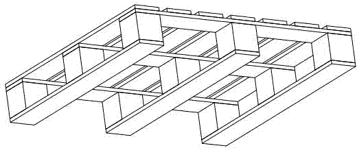
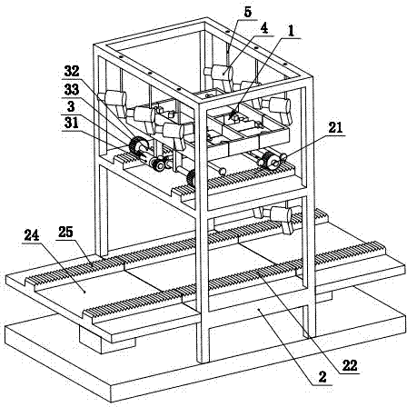
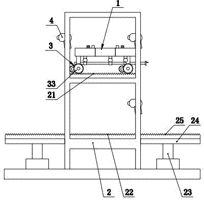
[0017] Such as figure 2 , 3 , 4, 5, and 6 show a wooden pallet binding equipment, including a wooden pallet binding assembly line, the wooden pallet binding assembly line carries multiple sets of wooden pallet stacking brackets 1, the wooden pallet binding assembly line The assembly line includes a rack 2. The rack 2 is provided with an upper row of racks 21 and a lower row of racks 22. The upper row of racks 21 is parallel to the lower row of racks 22 and is located in the lower row of racks. Directly above 22, each pair of wooden pallet stacking brackets 1 is connected with a driving device 3 that can drive it to move on the upper row of racks 21 or the lower row of racks 22, and the driving device 3 includes a motor 31 And the rotating shaft 32, the motor 31 and the rotating shaft 32 are all installed on the wooden pallet stacking bracket 1. The rotating shaft 32 is linked with the output shaft of the motor 31, and the rotating shaft 32 is provided with the upper row of racks. 21 or the rotating gear 33 on the lower row of racks 22 that engages and moves. A plurality of nail guns 4 are arranged above and below the upper row of racks 21, and the nail guns 4 are suspended from the machine by a drawstring 5. On the rack 2, the rack 2 is also provided with transfer cylinders 23 on both sides of the upper and lower rows of racks. The output end of the transfer cylinder 23 is provided with a transfer bracket 24, and the transfer bracket 24 is A movable rack 25 that can be spliced ​​with the upper row of racks 21 or the lower row of racks 22 is provided. The wooden pallet stacking bracket 1 is in the shape of Tian, ​​and the nine crossing angles of the wooden pallet stacking bracket 1 are respectively provided with nine foot posts that match the shape and size of the wooden pallet foot posts. Through groove 11, and one side of each foot post through groove 11 is also provided with a foot post pushing cylinder 12 for pushing the wooden pallet foot post to the foot post through groove 11, the wooden pallet stacking bracket 1 is also provided with a wood pushing cylinder 13 for pushing the wood pallet to be ordered onto the wooden pallet foot post. The Tian-shaped wooden pallet stacking bracket 1 is formed by splicing nine square plates 14 distributed in three horizontal rows and three vertical rows. The nine foot-post through grooves 11 are respectively opened in the nine square plates. On one square board 14, a square board control mechanism 15 is provided below the nine square boards 14 to control their mutual movement. The square plate control mechanism 15 can be composed of three horizontal sliding rods 151 and one longitudinal sliding rod 152. The three horizontal sliding rods 151 are respectively located under the three horizontal rows of square plates 14. The square plates 14 on each horizontal row are A horizontal sliding block 153 that can slide horizontally on the horizontal sliding rod 151 located below is connected, and each horizontal sliding rod 151 is connected with a longitudinal moving block 154 that can slide longitudinally on the vertical sliding rod 152. Of course, the square plate control mechanism 15 can also be constituted by three longitudinal sliding rods 152 and one horizontal sliding rod 151. The three longitudinal sliding rods 152 are respectively located under the three longitudinal rows of square plates 14, and the square on each longitudinal row The plates 14 are all connected with longitudinal sliding blocks that can slide longitudinally on the longitudinal sliding rods 152 located below them, and each longitudinal sliding rod 152 is connected with a lateral moving block that can slide laterally on the lateral sliding rods 151. In summary, the present invention provides a wooden pallet binding equipment that can greatly improve binding efficiency.

PUM

no PUM

Description & Claims & Application Information

We can also present the details of the Description, Claims and Application information to help users get a comprehensive understanding of the technical details of the patent, such as background art, summary of invention, brief description of drawings, description of embodiments, and other original content. On the other hand, users can also determine the specific scope of protection of the technology through the list of claims; as well as understand the changes in the life cycle of the technology with the presentation of the patent timeline. Login to view more.

Similar technology patents

Guide buckle and terminal sheath with same

ActiveCN102856728AImprove binding efficiencyCoupling device detailsEngineering
Owner:BYD CO LTD

Port binding method and system for multi-port USB equipment

PendingCN112650702AImprove binding efficiencySimple processElectric digital data processingEngineeringUSB
Owner:BEIJING HUADA ZHIBAO ELECTRONICS SYST +1

Information processing method, device and equipment and readable storage medium

ActiveCN112584350AImprove binding efficiencyReduce error rateParticular environment based servicesVehicle infrastructure communicationIntelligent transportIn vehicle
Owner:APOLLO INTELLIGENT CONNECTIVITY (BEIJING) TECH CO LTD

High-weather-resistance automotive paint

InactiveCN109627902AImprove weather resistanceImprove binding efficiencyAnti-corrosive paintsEpoxy resin coatingsChemical activityWeather resistance
Owner:安徽超哥精密科技有限公司

Classification and recommendation of technical efficacy words

  • Improve binding efficiency

Method and system for binding Internet of Things service machine card

PendingCN110446200AThe binding process is simpleImprove binding efficiencyNetwork data managementInternet of ThingsMSISDN
Owner:WATCHDATA SYST +1

Automatic rebar binding machine

PendingCN107587721AHigh degree of automationImprove binding efficiencyBuilding material handlingRebarAutomation
Owner:福建谊和天宸科技有限公司

Conversion layer large-span section steel concrete beam and construction method thereof

ActiveCN110700490AImprove binding efficiencyEasy to operateGirdersJoistsRebarLap joint
Owner:武汉市盘龙明达建筑有限公司
Why Eureka
Try Eureka