Steel wire hoisting gear in steel wire copper-plating production line

A lifting and landing device, production line technology, applied in liquid chemical plating, metal material coating process, coating and other directions, can solve problems affecting product quality and other issues, and achieve the effect of avoiding quality decline and improving product quality

Active Publication Date: 2014-01-08
张家港市中久金属制品有限公司
View PDF4 Cites 0 Cited by
  • Summary
  • Abstract
  • Description
  • Claims
  • Application Information

AI Technical Summary

Problems solved by technology

The coiled steel wire passes through the reaction solution in the copper plating tank sequentially under the joint action of the steel wire pay-off device and the steel wire take-up device. It is necessary to change the coil, that is, first place another coil of coil-shaped steel wire that is not copper-plated in the steel wire pay-off device, and then connect the starting end of the coil-shaped steel wire with the coil-shaped coil that is about to comple

Method used


Image

  • Steel wire hoisting gear in steel wire copper-plating production line
  • Steel wire hoisting gear in steel wire copper-plating production line

Examples


Example Embodiment

[0009] The present invention will be further described below in conjunction with the drawings and specific embodiments.

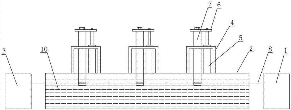
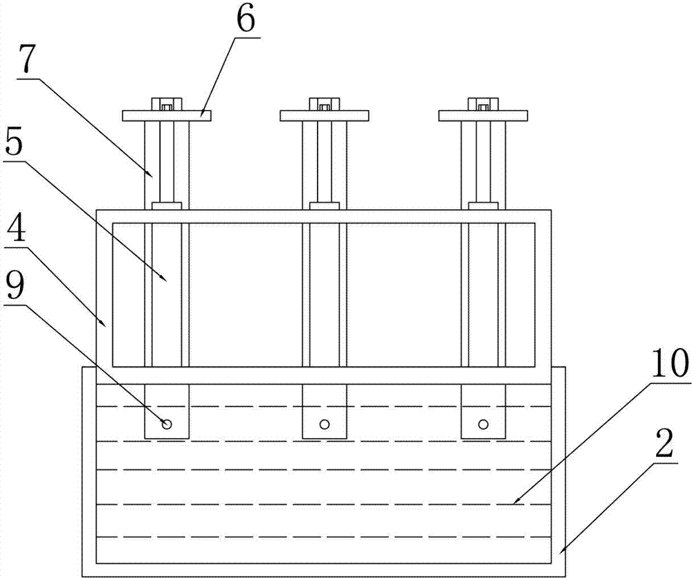
[0010] Such as figure 1 , figure 2 As shown, the steel wire lifting device in the steel wire copper plating production line includes a steel wire pay-off device 1, a copper plating tank 2 containing a reaction solution 10, and a steel wire take-up device 3 sequentially distributed along the running direction of the steel wire. In the running direction, at least one steel wire lifting line capable of raising and lowering the steel wire is provided above the copper plating tank 2. In this embodiment, three steel wire lifting lines are provided above the copper plating tank 2 along the steel wire running direction. In actual production The number of steel wire lifting lines can be adjusted according to actual production needs; each steel wire lifting line includes at least two spaced steel wire lifting mechanisms. In this embodiment, each steel wire lifting line...


PUM


Abstract

The invention discloses a steel wire hoisting gear in a steel wire copper-plating production line, which comprises a steel wire pay-off sequentially distributed in the steel wire running direction, a copper-plating tank filled with a reaction solution, and a steel wire take-up, wherein at least one steel wire hoisting strip line capable of hoisting the steel wire is arranged above the copper-plating tank in the steel wire running direction; each steel wire hoisting strip line at least comprises two steel wire hoisting mechanisms which are distributed at intervals; each steel wire hoisting mechanism comprises a mounting bracket installed on the top of the copper-plating tank; the mounting bracket is vertically provided with a retractable air cylinder; a piston rod of the retractable air cylinder is fixed with a mounting plate; the mounting plate is vertically provided with a drive rod; the lower end of the drive rod is provided with a through hole through which the steel wire can penetrate; and the stretching and retraction of the piston rod of the retractable air cylinder can synchronously drive the steel wire which penetrates through the corresponding drive rod to lift or immerge into the reaction solution in the copper-plating tank. The hoisting gear has the advantage of improving the product quality.

Description

technical field [0001] The invention relates to the technical field of metal surface treatment equipment, in particular to a steel wire lifting device in a steel wire copper plating production line. Background technique [0002] At the present stage, the steel wires coiled into discs are generally copper-plated on the surface of the steel wires through a steel wire copper-plating production line. Copper trough, and steel wire take-up device. The coiled steel wire passes through the reaction solution in the copper plating tank sequentially under the joint action of the steel wire pay-off device and the steel wire take-up device. In order to ensure the continuous production of the steel wire copper plating production line, when a coil of coiled steel wire is about to complete the copper plating operation, It is necessary to change the coil, that is, first place another coil of coil-shaped steel wire that is not copper-plated in the steel wire pay-off device, and then connect ...

Claims


Application Information

Patent Timeline
IPC IPC(8): C23C18/38
Inventor 蒋永华蒋卫华唐明
Owner 张家港市中久金属制品有限公司
Why Eureka
Try Eureka