Engine air distribution mechanism abrasion testing device

A gas distribution mechanism and wear test technology, applied in the direction of internal combustion engine testing, etc., can solve the problems of multi-material force, long test cycle of engine bench, long time, etc., and achieve the effect of less material force, short test cycle and convenient adjustment

Active Publication Date: 2014-01-08
济南沃德汽车零部件有限公司
View PDF8 Cites 12 Cited by
  • Summary
  • Abstract
  • Description
  • Claims
  • Application Information

AI Technical Summary

Problems solved by technology

Conventional engine bench tests have a long period and are generally carried out after the design is completed, which requires a long time and a lot of material resources

Method used


Image

  • Engine air distribution mechanism abrasion testing device
  • Engine air distribution mechanism abrasion testing device
  • Engine air distribution mechanism abrasion testing device

Examples


Embodiment 1

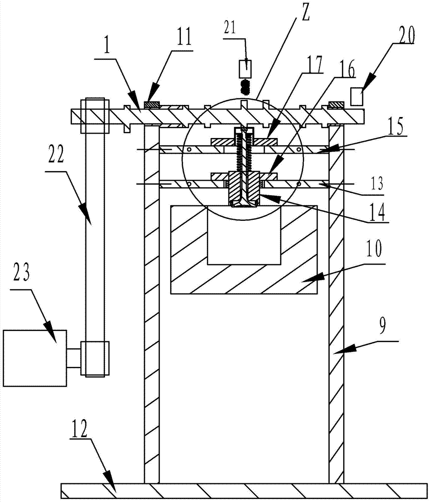
[0019] Embodiment 1, a kind of engine gas distribution mechanism wear test device is characterized in that: the horizontal base 12 is provided with two mutually parallel uprights 9, and the camshaft 1 with driving device is installed on the top of the uprights, between the two uprights An upper horizontal bracket 15 and a lower horizontal bracket 13 for fixing the valve train are installed,

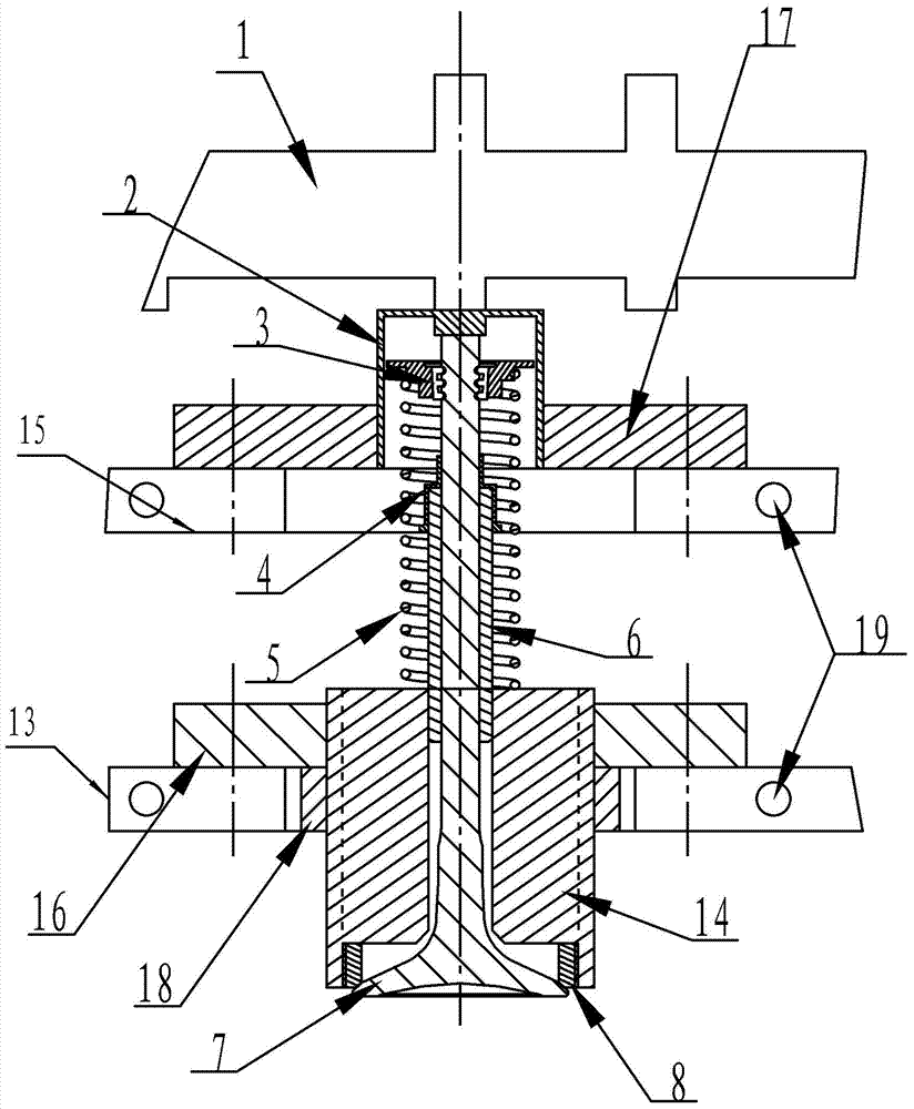
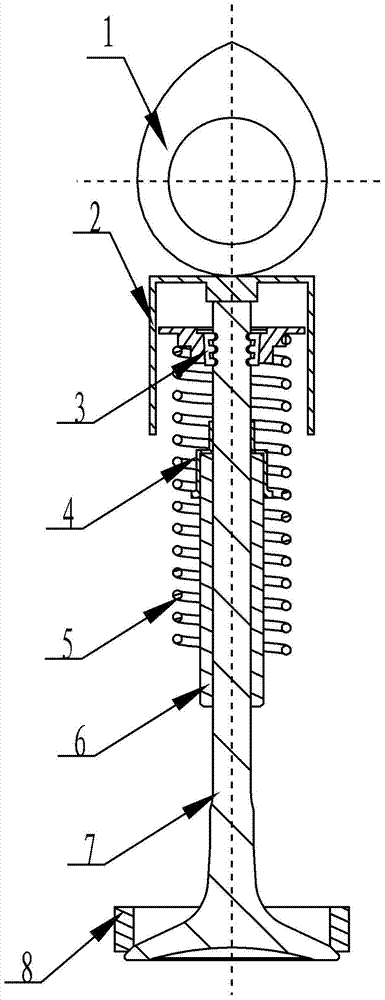
[0020] The valve lifter 2 is installed at the end of the vertically upward valve 7 of the valve distribution mechanism, the valve guide 6 is installed in the inner hole of the seat ring seat 14, and the valve spring 4 is set on the valve lock clip 3 together with the spring seat. The valve seat ring 8 is installed in the seat ring seat 14,

[0021] The upper horizontal bracket is equipped with a guide plate 17, the lower horizontal bracket is equipped with a positioning plate 16, the seat ring seat 14 passes through the center hole of the positioning plate, and is fixed on the lower side ...

Embodiment 2

[0022] Embodiment 2, a kind of engine gas distribution mechanism wear test device is characterized in that: two mutually parallel uprights 9 are arranged on the horizontal base 12, the camshaft 1 with driving device is installed on the top of the uprights, between the two uprights An upper horizontal bracket 15 and a lower horizontal bracket 13 for fixing the valve train are installed,

[0023] The valve lifter 2 is installed at the end of the vertically upward valve 7 of the valve distribution mechanism, the valve guide 6 is installed in the inner hole of the seat ring seat 14, and the valve spring 4 is set on the valve lock clip 3 together with the spring seat. The valve seat ring 8 is installed in the seat ring seat 14,

[0024] The upper horizontal bracket is equipped with a guide plate 17, and the lower horizontal bracket is equipped with a positioning plate 16. The seat ring seat 14 passes through the center hole of the positioning plate, and is fixed on the lower side o...


PUM


Abstract

The invention discloses an engine air distribution mechanism abrasion testing device, which belongs to engine testing equipment and particularly relates to a device used for the abrasion testing of an engine air distribution mechanism. The engine air distribution mechanism abrasion testing device is characterized in that two mutually parallel upright posts are arranged on a horizontal base, the tops of the upright posts are provided with a cam shaft with a driving device, an upper transverse support frame and a lower transverse support frame used for fixing an air valve air distribution mechanism are arranged between the two upright posts, a guide plate is arranged on the upper transverse support frame, a positioning plate is arranged on the lower transverse support frame, a seat ring seat sheathed on an air valve seat ring passes through a center hole of the positioning plate, a fastening screw nut fixedly arranged at the lower side of the positioning plate is connected with the seat ring seat through screw threads, and an air valve catheter is arranged in an inner hole of the seat ring seat. The testing device has the advantages that the abrasion condition of each part of the engine air distribution mechanism under the actual operation conditions can be completely simulated, and the support is provided for the final design of the engine air distribution mechanism.

Description

technical field [0001] The invention belongs to engine test equipment, in particular to a device for wear test of an engine valve train. Background technique [0002] The gas distribution mechanism of an internal combustion engine is an important part of the engine. It mainly consists of camshafts, tappets, valves, valve seat rings, conduits, springs, spring seats, lock clips, sealing rings and other parts. The main matching surfaces in the gas distribution mechanism are Camshaft and tappet upper surface, valve stem end surface and tappet inner surface, valve stem outer surface and guide tube inner surface, valve cone surface and valve seat ring cone surface, valve lock clip groove and lock clip, seal ring inner surface and The outer surface of the valve stem, these mating surfaces are in high-speed reciprocating motion and high temperature during work and bear a certain spring force, so wear between the mating surfaces is inevitable. When the wear is serious, the power per...

Claims


Application Information

Patent Timeline
Patent Type & Authority Applications(China)
IPC IPC(8): G01M15/04
Inventor 曲文强董兵肖学林聂元龙陶子祥张杰陈雪萍
Owner 济南沃德汽车零部件有限公司
Why Eureka
Try Eureka