
A full range transient electromagnetic synchronous sounding device

A transient electromagnetic and depth-sounding technology, applied in measuring devices, electric/magnetic exploration, radio wave measurement systems, etc., can solve the problems of reducing the resolution of TEM methods and losing the ability of TEM methods to detect shallow structures, and achieve The detection construction is convenient, the mutual inductance effect is reduced, and the detection effect is improved.

Active Publication Date: 2016-08-31
ANHUI HUIZHOU GEOLOGY SECURITY INST
View PDF6 Cites 0 Cited by
  • Summary
  • Abstract
  • Description
  • Claims
  • Application Information

AI Technical Summary

Problems solved by technology

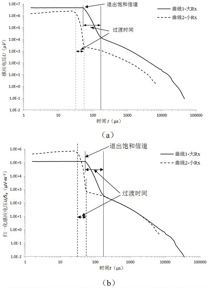
[0003] For the time domain, the detection depth is determined by the time of observation. At present, almost all the late signals are recorded by TEM instruments, or only late signals are used in data processing. This situation will have two consequences: first , it loses the ability of the TEM method to detect the shallow structure, because the information of the shallow structure is mainly carried by the early signal; second, it reduces the resolving power of the TEM method, because the influence of the current shutdown will distort the transient response , therefore, in the actual measurement, people discard the distorted early signal, and only record the late signal after this moment, the effective detection depth is only below the depth that the signal can propagate at this moment, and there is a detection blind zone

Method used


Image

  • A full range transient electromagnetic synchronous sounding device
  • A full range transient electromagnetic synchronous sounding device
  • A full range transient electromagnetic synchronous sounding device

Examples


Embodiment 1

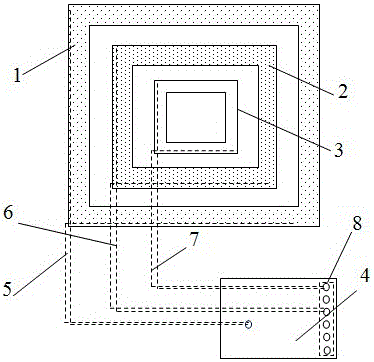
[0017] Embodiment one: if figure 1 As shown, the present invention includes a transmitting coil 1 , dual receiving coils and a matched multi-channel receiver 4 . The double receiving coil is composed of the first receiving coil 2 and the second receiving coil 3; the first receiving coil 2 is located in the transmitting coil 1, and the second receiving coil 3 is located in the first receiving coil 2; the transmitting coil 1, the first receiving coil 2 The third receiving coil 3 and the second receiving coil 3 are in the same plane and are spaced apart from each other. The size of the transmitting coil 1 is larger than that of the double receiving coils; the number of turns of the first and second receiving coils is multiple turns, but the size and total area of ​​the first receiving coil are larger than that of the second receiving coil 3 . The transmitting coil 1 and the double receiving coils are combined in the form of a common center point; the first receiving coil 2 and t...

Embodiment 2

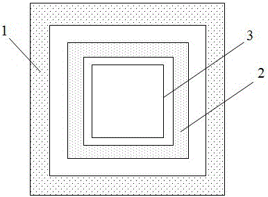
[0018] Embodiment two: if figure 2 As shown, the difference from Embodiment 1 is that the dual receiving coils consist of a first receiving coil 2 with a large size, multiple turns, and a large receiving area and a second receiving coil 3 with a small size, single turn, and a small receiving area. The transmitting coil and the receiving coil are combined in the form of a common center point; the multi-channel receiver is connected to the first and second receiving coils respectively. Synchronous acquisition of lap signals.

Embodiment 3

[0019] Embodiment 3: The difference from Embodiment 1 is that the transmitting and receiving coils can be wound in various ways, such as parallel winding, cross winding, double stack winding, or Chain winding method.


PUM


Abstract

The invention discloses a full range transient electromagnetic synchronous sounding device, comprising a transmitting coil, a double receiving coil and a matching multi-channel receiver; the double receiving coil is composed of a first receiving coil and a second receiving coil, The second receiving coil is located in the first receiving coil and both are in the same plane, adopting the form of a common center point; the transmitting coil is located on the periphery of the dual receiving coils. Combined in the form of a common center point or a common central axis and keep a gap between them. The invention can realize synchronous acquisition of double coil signals. The size of the transmitting coil is larger than that of the receiving coil, which can reduce the influence of mutual inductance, improve the signal-to-noise ratio and sensitivity; the double receiving coil-dual-channel synchronous measurement device can realize the effective measurement of the late field signal and the early field signal respectively, so as to ensure the deep On the basis of the detection ability, the detection blind area is reduced, and the shallow detection effect is improved; the traditional center loop measurement device is not changed, and the detection construction is convenient.

Description

technical field [0001] The invention relates to a transient electromagnetic full-depth measuring device, in particular to a full-range transient electromagnetic synchronous sounding device. Background technique [0002] The transient electromagnetic method belongs to the time-domain electromagnetic method (TEM), which is a time-domain artificial source electromagnetic detection method based on the principle of electromagnetic induction. Using an ungrounded loop (magnetic source) or a grounded line source (galvanic source) to send a pulsed magnetic field underground, under its excitation, the induced eddy current excited in the underground geological body will generate an induced electromagnetic field that changes with time (secondary Field), according to the characteristics of the quadratic field attenuation curve to judge the electrical properties, scale, and occurrence of underground geological bodies (citation: Niu Zhilian. Principles of time-domain electromagnetic method...

Claims


Application Information

Patent Timeline
Patent Type & Authority Patents(China)
IPC IPC(8): G01V3/10
Inventor 倪圣军唐润秋刘家莲李纯阳魏帮俊任云胡雄武吴昭
Owner ANHUI HUIZHOU GEOLOGY SECURITY INST
Learn More