
Total-stroke and total-space transient electromagnetic device and measuring method
A transient electromagnetic, full-space technology, applied in the direction of electrical/magnetic detection for logging records, to reduce the influence of self-inductance and mutual inductance, facilitate real-time imaging, and improve the effect of shallow detection
- Summary
- Abstract
- Description
- Claims
- Application Information
AI Technical Summary
Problems solved by technology
Method used
Image

Examples
Embodiment 1
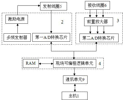
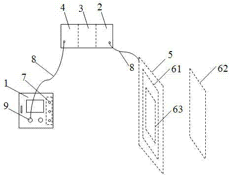
[0037] Embodiment one: if figure 1 , figure 2 As shown, the present invention includes a host 1 , a transmitting unit 2 , a multi-channel receiving unit 3 , a signal processing unit 4 and a communication unit 9 . Both the transmitting unit 2 and the multi-channel receiving unit 3 are respectively connected with the signal processing unit 4, and the signal processing unit 4 is connected with the host computer 1 through the communication unit. Host 1 is used to set the acquisition parameters and configuration channel parameters, and record, display and manage the received data. It adopts ARM quad-core processor and can analyze data in real time; host 1 is set with multiple channel communication ports 7, which can Receive measurement data synchronously. Transmitting unit 2 includes a multi-frequency transmitter, the first A / D conversion chip and an excitation power supply for supplying power to transmitting coil 5; multi-channel receiving unit 3 includes a preamplifier connec...
Embodiment 2
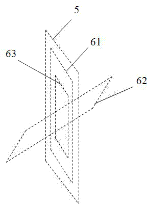
[0040] Embodiment two: if image 3 As shown, the difference from Embodiment 1 is that the sub-receiving coil and the main and sub-receiving coils are placed in an orthogonal or oblique manner. Wherein, the transmitting coil shares a center point with the main receiving coil and the sub receiving coil, and the sub receiving coil may or may not share a center point with the main receiving coil, the sub receiving coil and the transmitting coil.
Embodiment 3
[0041] Embodiment three: as Figure 4 As shown, the difference from Embodiment 1 is that the receiving coil consists of two parallel receiving coils to form a double receiving coil, that is, the main receiving coil 61 and the auxiliary receiving coil 62, the two receiving coils have the same area and the main receiving coil 61 and the auxiliary receiving coil There is a certain distance between the receiving coils 62; the transmitting coil is placed outside the main receiving coil 61 and has a common center with it.
PUM
 Abstract
Description
Claims
Application Information