
Sequential control method for landing obstacle avoidance of lunar probe

A timing control and detector technology, applied in two-dimensional position/channel control and other directions, can solve problems such as real-time and autonomy not meeting the requirements of use, image processing unit processing time differences, and affecting the efficiency of the obstacle avoidance process, etc., to achieve Orderly and seamless connection, compressed waiting time, high real-time effects

Active Publication Date: 2014-01-08
BEIJING INST OF CONTROL ENG
View PDF3 Cites 8 Cited by
  • Summary
  • Abstract
  • Description
  • Claims
  • Application Information

AI Technical Summary

Problems solved by technology

However, for the lunar obstacle identification and safe landing area selection tasks of the probe, its real-time and autonomy are far from meeting the requirements of use.
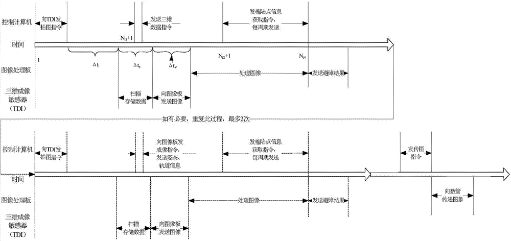
In the traditional way, after the control computer sends the imaging command, it sends the information required for image processing to the image processing unit at a fixed time interval, and then retrieves the security point identification information from the image processing unit at a fixed time interval. Leave a long time for image processing and obstacle recognition. Due to the terrain differences in the imaging area and the brightness conditions at the imaging moment, the processing time of the image processing unit for the image is also different.
Too long reserved time will affect the efficiency of the subsequent obstacle avoidance process, and too short reserved time may lead to the failure of the obstacle avoidance task. Therefore, the traditional method has certain defects in terms of efficiency and flexibility.

Method used


Image

  • Sequential control method for landing obstacle avoidance of lunar probe
  • Sequential control method for landing obstacle avoidance of lunar probe

Examples


Embodiment Construction

[0022] There are relatively dense impact craters in the intended landing area of ​​the moon. In order to ensure the safe landing of the probe and meet the requirements of the safe landing terrain, it is necessary to use imaging sensors to actively detect the features of the lunar surface during the landing process, to detect and avoid terrain obstacles in time, and to plan safety. , reasonable descent trajectory and target landing area.

[0023]During the landing process, the entire obstacle avoidance process is composed of two stages of rough obstacle avoidance and fine obstacle avoidance, interspersed with guidance and control links in the middle, and the probe is approached to the target landing point according to a specific guidance law. When the detector's height, speed, attitude and other conditions meet the requirements of optical imaging, start the rough obstacle avoidance process of optical imaging, start imaging, image processing, obstacle identification, and determin...


PUM


Abstract

The invention relates to a sequential control method for landing obstacle avoidance of a lunar probe. The sequential control method comprises the steps that during a rough obstacle avoidance stage, a sequential control method of an optical imaging sensor is adopted, during a fine obstacle avoidance stage, a sequential control method of a three-dimensional imaging sensor is adopted, a guidance control link is interpenetrated in the middle, and the probe is enabled to approach to a target landing point according to specific guidance rules. When the conditions such as the height, the speed and the posture of the probe meet the optical imaging requirement, an optical imaging rough obstacle avoidance process is started, imaging, image processing, obstacle recognition and landing safety region determination are performed, and the probe is enabled to approach to a safe landing region according to obstacle avoidance results in a descending process. When the conditions such as the height, the speed and the posture of the probe meet the three-dimensional imaging requirement, a three-dimensional fine obstacle avoidance flow process is started, the target landing safety point is finally determined, the probe finally reaches a part above the target landing point according to obstacle avoidance results, and the whole obstacle avoidance flow process is completed.

Description

technical field [0001] The invention relates to a control method when a probe avoids obstacles during a soft landing on the moon. Background technique [0002] The mission characteristics and environmental conditions of the soft landing determine that the landing process of the lunar probe is short, while the ground measurement and control time delay is large. The soft landing mission must not only ensure high landing safety, but also adapt to the lunar surface environment. Therefore, the GNC subsystem is required to quickly and accurately identify obstacles in the landing area during the descent of the probe, and finally determine a safe landing point. [0003] During the landing process, the task of identifying lunar obstacles and selecting a safe landing area is jointly completed by the control computer (CCU), image processing unit, optical imaging sensor and three-dimensional imaging sensor (TDI). There are command sending, information interaction and image data transmi...

Claims


Application Information

Patent Timeline
IPC IPC(8): G05D1/02
Inventor 梁俊程铭于洁杨巍赵宇何健于萍王大轶张洪华
Owner BEIJING INST OF CONTROL ENG
Learn More