Fault locating method and device

A fault location and fault information technology, applied in the computer field to reduce maintenance costs

Inactive Publication Date: 2014-01-08
HUAWEI TECH CO LTD
View PDF8 Cites 27 Cited by
  • Summary
  • Abstract
  • Description
  • Claims
  • Application Information

AI Technical Summary

Problems solved by technology

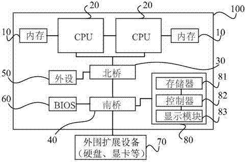
[0008] This prior art requires an additional controller 82 and a display module 83, through which the display module 83 displays the self-inspection information in t

Method used


Image

  • Fault locating method and device
  • Fault locating method and device
  • Fault locating method and device

Examples


Embodiment Construction

[0051] In order to make the purpose, technical solutions and advantages of the embodiments of the present invention clearer, the technical solutions in the embodiments of the present invention will be clearly and completely described below in conjunction with the drawings in the embodiments of the present invention. Obviously, the described embodiments It is a part of embodiments of the present invention, but not all embodiments. Based on the embodiments of the present invention, all other embodiments obtained by persons of ordinary skill in the art without making creative efforts belong to the protection scope of the present invention.

[0052] With the widespread use of servers, a large number of servers will be deployed in a data center or computer room, and the running status of the servers is usually monitored remotely outside the computer room. Therefore, it is necessary to remotely collect and monitor fault information in the POST phase.

[0053] image 3It is a flow c...


PUM


Abstract

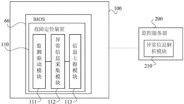
The embodiment of the invention provides a fault locating method and device. The fault locating method includes the steps that when a power-on starting device performs a BIOS program of a basic input and output system, monitoring is performed on hardware abnormity triggering conditions; when the hardware abnormity triggering conditions are monitored, abnormity information is collected, and the abnormity information at least comprises fault information of a central processing unit (CPU); the abnormity information is reported to a monitoring server through a network. Examining and accurate locating performed on the fault information are achieved in a remote mode.

Description

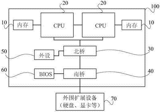
technical field [0001] The embodiments of the present invention relate to computer technology, and in particular to a fault location method and device. Background technique [0002] The reliability of computer systems, especially server products, has always been a hot topic. If the server fails, it needs to be detected, located, and eliminated in time. This requires that the server can be conveniently used when the server does not have the function of a standard cathode ray tube (CRT) or liquid crystal display (LCD). The failure information is presented to the user. At this point, it is very important to collect and locate fault information in the Power On Self-Test (POST) stage. [0003] The logic block diagram of a typical computer or server is as follows: figure 1 As shown, the motherboard 100 includes: a memory 10 , a CPU 20 , a north bridge 30 , a south bridge 40 , peripherals 50 and a Basic Input and Output System (BIOS for short) 60 . In addition, the motherboard ...

Claims


Application Information

Patent Timeline
IPC IPC(8): G06F11/22G06F11/34
CPCG06F11/2284
Inventor 刘通良姜广吉陈俊杰
Owner HUAWEI TECH CO LTD
Why Eureka
Try Eureka