Eureka AIR delivers breakthrough ideas for toughest innovation challenges, trusted by R&D personnel around the world.

Medical communication call equipment host

A technology for calling equipment and hosts, which is applied in the field of hospital nursing communication systems. It can solve the problems of insufficient power supply capacity of the host, increase the difficulty of installation and maintenance, and increase the complexity of the system. It can increase the number of broadcasting extensions, ensure undistorted transmission, and standby function The effect of low consumption

Active Publication Date: 2015-12-02
山东亚华电子股份有限公司
View PDF6 Cites 0 Cited by
  • Summary
  • Abstract
  • Description
  • Claims
  • Application Information

AI Technical Summary

Problems solved by technology

[0004] The above patents use a two-wire power supply. The audio transmission of this patent does not affect the command transmission between the host and the extension; however, the extension is powered by a power amplifier, which limits the use of the device when the load increases; resulting in the power supply capacity of the host. Insufficient, the load capacity is not strong, or by adding an amplifier, or by adding a power supply, which increases the complexity of the system and increases the difficulty of installation and maintenance; and the host uses a plus or minus 15V power supply, which is not easy to expand to other voltage power supplies

Method used


Image

  • Medical communication call equipment host
  • Medical communication call equipment host

Examples


Embodiment 1

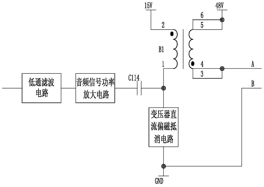
[0025] Such as figure 1 As shown, the shell of the medical communication and calling equipment host has a built-in telephone module, a low-pass filter circuit, an audio signal power amplifier circuit, an audio signal coupling circuit, and a transformer DC bias offset circuit. The circuit, the audio signal power amplifier circuit and the audio signal coupling circuit are connected to one of the two-wire buses, and the input end of the audio signal coupling circuit is connected to the other one of the two-wire buses through the DC bias cancellation circuit of the transformer; the audio signal sent by the telephone module passes through After low-pass filtering, the audio signal is amplified by the audio signal power amplifier circuit, and then the audio signal is coupled to the two-wire bus through the audio signal coupling circuit, and the audio signal is sent to the extension terminal through the two-wire bus; the offset magnetic bias circuit is based on the two-wire system Th...

Embodiment 2

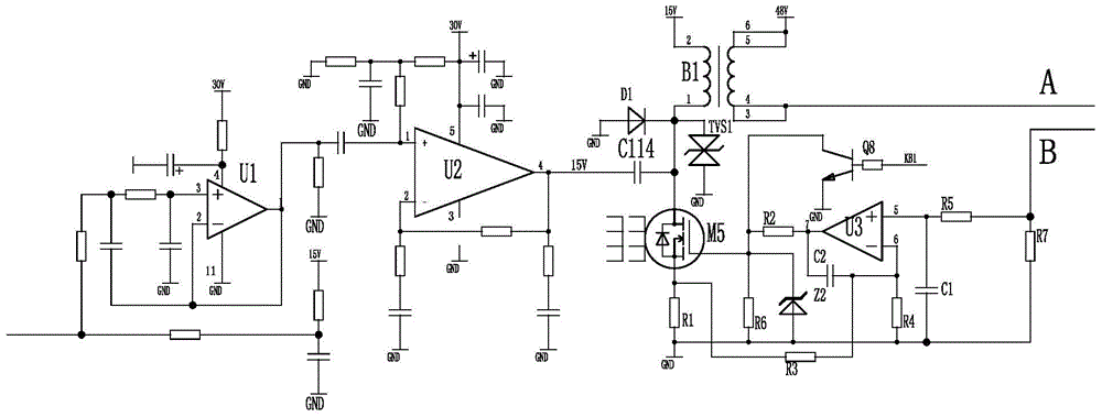
[0028] On the basis of Embodiment 1, the audio signal coupling circuit includes an audio coupling transformer B1 and a coupling capacitor C114, the secondary end of the audio coupling transformer B1 is connected to a 48V power supply, and the secondary end of the same name is connected to one of the two-wire buses (line A ); the primary end of the audio coupling transformer B1 with the same name is connected to the 15V power supply, the non-identical end is connected to the output end of the audio signal power amplifier circuit through the coupling capacitor C114, and the primary non-identical end of the audio coupling transformer is connected to the transformer DC bias cancellation circuit.

Embodiment 3

[0030] On the basis of Embodiments 1 and 2, the transformer DC bias offset circuit applies a DC current inversely proportional to the number of turns of the transformer coil to both sides of the audio coupling transformer to offset the influence of the DC bias on the sound signal.

[0031] The turn ratio of the primary coil to the secondary coil of the audio coupling transformer of the audio signal coupling circuit is 8:1. The audio coupling transformer B1 is a transformer made of silicon steel sheet magnetic core material. The working frequency of this transformer is low frequency to meet the needs of the system. Stable performance. The turn ratio of the primary coil to the secondary coil is 8:1, and the bias magnetic effect cancellation circuit only needs a current of 1 / 8 of the bus current to offset the bias magnetic effect, so that the audio signal can be increased by reducing the amplitude of the audio voltage current carrying capacity. Due to the relatively large bus c...


PUM


Abstract

The invention discloses a medical communication calling device mainframe, and belongs to the field of nursing communication systems for a hospital. The medical communication calling device mainframe comprises a shell and is characterized in that a phone module, a sound signal power amplifying circuit, a sound signal coupling circuit and a transformer DC magnetic bias bucking circuit are arranged inside the shell; sound signals pass through the sound signal power amplifying circuit and are coupled to a two-wire system bus through a voice frequency coupling transformer, and the sound signals are sent to extension set terminals through the two-wire system bus. According to the medical communication calling device mainframe, under the condition that a large DC load can exist on the output side of the voice frequency coupling transformer, the sound signals are smoothly coupled to the two-wire system bus, the signal distorting phenomenon caused by magnetic biasing of the voice frequency coupling transformer under the large DC load is removed, and power consumption in a standby state is extremely low. The medical communication calling device mainframe can be widely applied to hospital ward communication calling and hospital queuing and calling systems.

Description

technical field [0001] The invention provides a host of medical communication calling equipment, which belongs to the field of hospital nursing communication systems. Background technique [0002] The communication call system between patients and nurses in hospital wards, its two-wire bus has been recognized by the majority of users because of its advantages of less wiring, simple wiring, convenient installation, and easy maintenance; the traditional extension has only one indicator light, and the power consumption is very small , the implementation is relatively simple; but now extensions generally have LCD screens, the current of the bus is getting larger and larger, and the transmission of call audio signals becomes very difficult under the condition of high voltage and high current. The current common method is to reduce the current of the bus by adding an external power supply or an amplifier. This solution reduces the stability of the system, increases the difficulty ...

Claims


Application Information

Patent Timeline
IPC IPC(8): H04M9/00H04M19/00
CPCY02D30/70
Inventor 宋庆陈磊
Owner 山东亚华电子股份有限公司
Why Eureka
Eureka Blog
Learn More