Household floor cleaning machine

A technology for household floors and cleaning machines, applied in the field of cleaning appliances, can solve the problems of unsatisfactory vacuuming effect, unsuitable for ordinary households, poor cleaning effect, etc. Effect

Active Publication Date: 2014-01-15
如东县东广物流有限公司
View PDF5 Cites 8 Cited by
  • Summary
  • Abstract
  • Description
  • Claims
  • Application Information

AI Technical Summary

Problems solved by technology

[0002] At present, vacuum cleaners are the main cleaning machines suitable for household use, but the principle of vacuum cleaners is to use air flow to remove paper dust. The cleaning effect on the stains on the floor is poor. At the same time, the high-power vacuum cleaner is noisy and consumes a lot of energy, so it is not suitable for home use.
The vacuum cleaner is mainly suitable for the condition of the carpet. The floor of the general family is still mainly mopped. The effect of vacuuming is not ideal, and the condition of the floor is suitable for mopping.
However, the existing cleaning machines that satisfy the function of mopping the floor are generally larger in size and higher in cost, and are only suitable for use in large public places, not for ordinary families.

Method used


Image

  • Household floor cleaning machine
  • Household floor cleaning machine

Examples


Embodiment 1

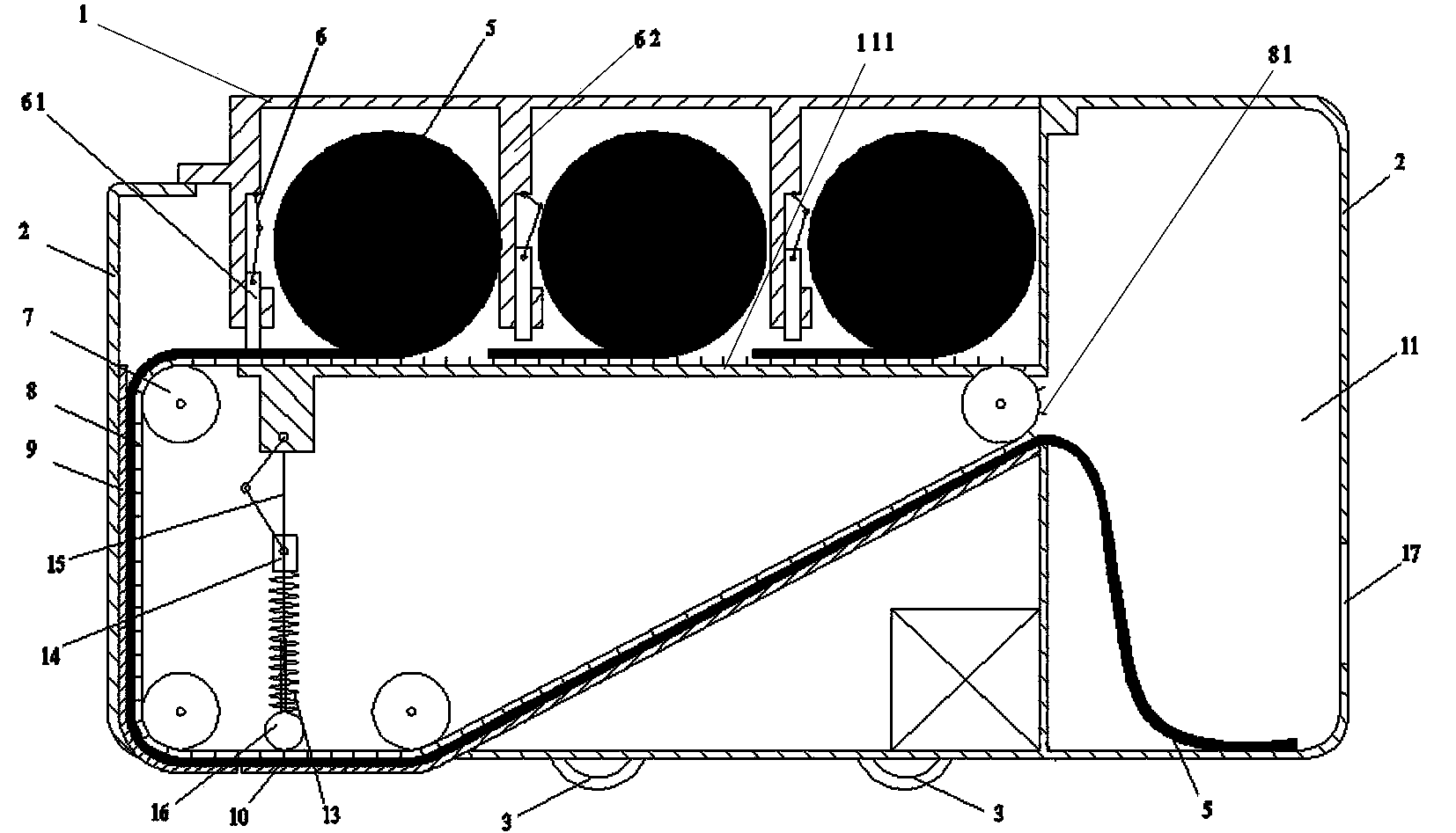
[0031] A household floor cleaning machine, comprising a car body 2, a wheel 3 arranged at the bottom of the car body 2, a towel box arranged on the upper part of the car body for holding towels 5, a transmission assembly for transferring towels 5 located below the towel box, The conveying pressing part for pressing the towel in the towel box onto the conveying assembly, the pressing assembly for pressing down the towel 5 conveyed by the conveying assembly to the bottom of the car body, and the dirty towel storage box 11 for placing dirty towels , The dirty towel storage box 11 is provided with a dirty towel inlet and a dirty towel outlet 17, and the bottom of the vehicle body 2 is provided with a towel press-down outlet corresponding to the lower part of the press-down assembly. The transmission assembly includes several timing pulleys 7, a timing belt 8 sheathed on the timing pulleys 7, and a transmission track cooperating with the timing belt 8 to convey the towel 5. The syn...

Embodiment 2

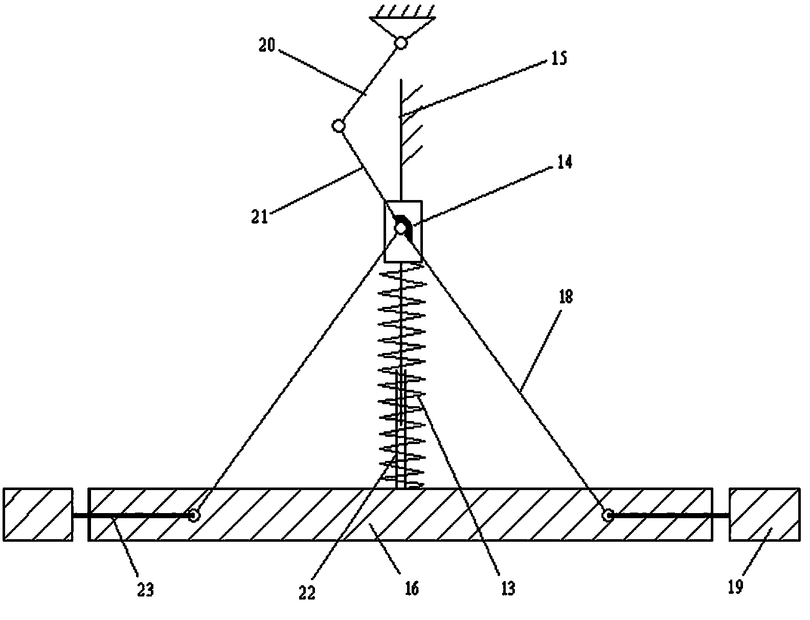
[0038] The main cleaning pressure head 16 is a square flat pressure head, and the front and rear ends of the main cleaning pressure head 16 are provided with protruding cleaning pressure heads 19, and the front and rear ends of the main cleaning pressure head 16 are provided with protruding pressure head slide rails 23 , the overhanging cleaning head 19 is connected with the main cleaning head 16 through a slide bar arranged on the overhanging head slide rail 23, and the lower pressing assembly also includes a strut 18, and the upper and lower ends of the strut 18 are respectively hinged on the slide Block 14 and slider on.

[0039] Connecting rod one 20 is connected on the car body, and slide rail 15 is fixed on the car body, and connecting rod one 20, connecting rod two 21, slide block 14 and slide rail 15 have formed the slider crank mechanism, and the overhang cleaning pressure head 19 can Sliding telescopically to both ends along the outwardly extending pressure head slid...


PUM


Abstract

The invention belongs to a cleaning appliance and particularly relates to a household floor cleaning machine which is suitable for household use. The household floor cleaning machine is characterized by comprising a vehicle body, a towel box arranged at the bottom of the vehicle body, a transport component, a conveying and pushing part, a pushing component for pushing a towel transported by the transport component to the bottom of the vehicle body, and a dirty towel storage box for storing dirty towels, wherein the dirty towel storage box is provided with a dirty towel inlet and a dirty towel outlet, and a towel pushing outlet is formed in the position, corresponding to the lower part of the pushing component, at the bottom of the vehicle body. The cleaning machine cleans the ground by automatically transporting and pushing the towel, is in tight contact with the ground, has a good cleaning effect. The transport is convenient and smooth, and jamming is not likely to happen. The equipment cannot be easily damaged and is long in service life. The cleaning machine is simple in structure, low in cost, high in degree of automation and good in cleaning effect.

Description

technical field [0001] The invention belongs to the category of cleaning appliances, and in particular relates to a household floor cleaning machine suitable for family use. Background technique [0002] At present, vacuum cleaners are the main cleaning machines suitable for household use, but the principle of vacuum cleaners is to use air flow to remove paper dust. The cleaning effect on the stains on the floor is poor. At the same time, a vacuum cleaner with high power is noisy and consumes a lot of energy, so it is not suitable for home use. The vacuum cleaner is mainly suitable for the condition of the carpet. The floor of the general family is still mainly mopped. The effect of vacuuming is not ideal, and the condition of the floor is suitable for the mode of mopping. However, the existing cleaning machines that satisfy the mopping function are generally larger in size and higher in cost, and are only suitable for use in large public places and are not suitable for ord...

Claims


Application Information

Patent Timeline
Patent Type & Authority Applications(China)
IPC IPC(8): A47L11/26A47L11/40
Inventor 魏翠琴朱建伟高志宏贾少刚蒉秀惠陆雄雄王丽萍
Owner 如东县东广物流有限公司
Why Eureka
Try Eureka