
Dispensing machine and method for correcting position of dispensing needle

A calibration method and technology for dispensing machines, applied in the field of dispensing machines, can solve problems such as easy deviation, wrong dispensing path, affecting product quality, etc.

Inactive Publication Date: 2014-01-15
HONG FU JIN PRECISION IND (SHENZHEN) CO LTD +1
View PDF0 Cites 16 Cited by
  • Summary
  • Abstract
  • Description
  • Claims
  • Application Information

AI Technical Summary

Problems solved by technology

However, due to the error caused by manual replacement, the dispensing needle before and after the replacement is prone to deviation relative to the rubber cartridge, which will lead to errors in the dispensing path and affect the quality of the product

Method used


Image

  • Dispensing machine and method for correcting position of dispensing needle
  • Dispensing machine and method for correcting position of dispensing needle
  • Dispensing machine and method for correcting position of dispensing needle

Examples


Embodiment Construction

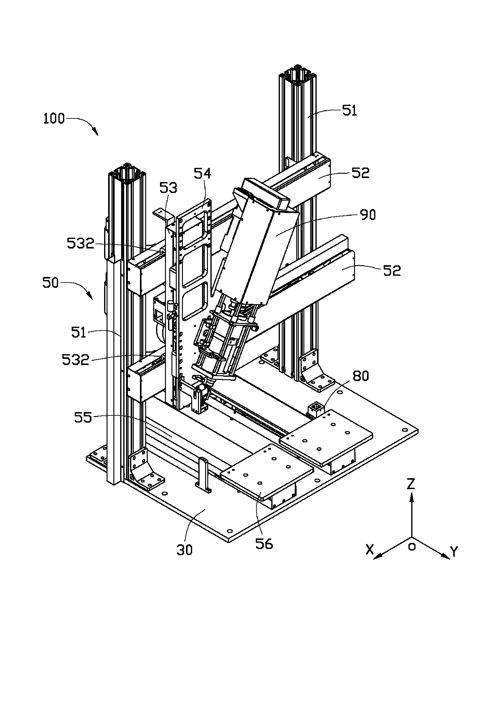
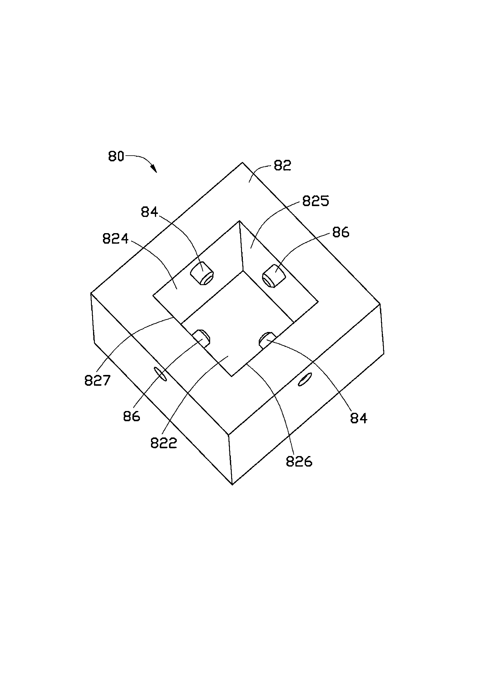
[0016] see figure 1 , a preferred embodiment of the present invention provides a glue dispenser 100 for dispensing various products (such as mobile phone casings). The dispenser 100 includes a base 30 , a moving component 50 , a sensing component 80 and a dispensing component 90 .

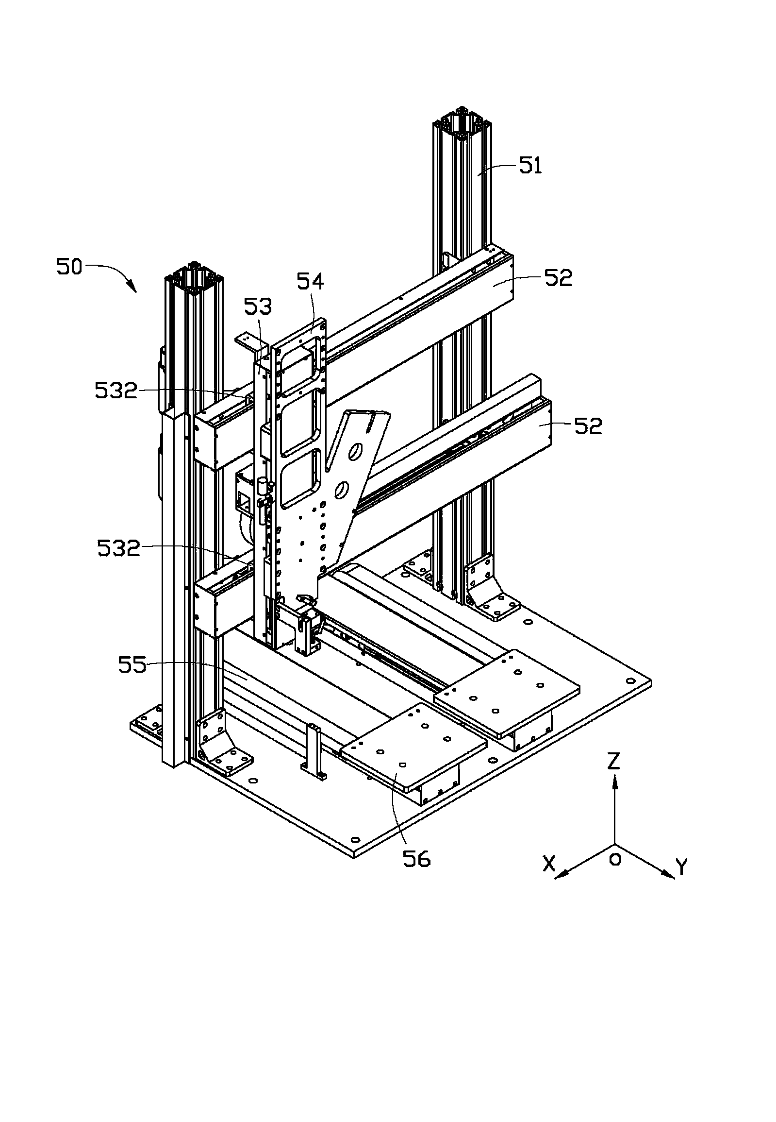
[0017] see figure 2 , the moving assembly 50 is disposed on the base 30 and is used to drive the dispensing assembly 90 to move in the directions of the X-axis, Y-axis and Z-axis. The moving assembly 50 includes two cylinders 51 , two fixing plates 52 , a connecting plate 53 , a sliding plate 54 , two guiding plates 55 and two carrying platforms 56 . The two cylinders 51 are vertically disposed on the base 30 , and the two fixing plates 52 are parallelly disposed on the two cylinders 51 . The connecting plate 53 is slidably arranged on the two fixing plates 52. In this embodiment, two sets of guide rails 532 are arranged on the connecting plate 53, and each set of guide rails 532 is assembled o...


PUM


Abstract

The invention provides a dispensing machine, comprising a mobile assembly, a sensing assembly and a dispensing assembly, wherein the sensing assembly comprises a positioning seat, and a first raster and a second raster which are arranged on the positioning seat. The first raster and the second raster transmit light beams, the dispensing assembly is arranged on the mobile assembly, and the dispensing assembly comprises an electric control unit, a drive mechanism and a dispensing needle, wherein the electrical control unit is electrically connected with the drive mechanism, the drive mechanism is used for driving the dispensing needle to move, the mobile assembly drives the dispensing needle close to the positioning seat in order to shield the light beams from the first raster and the second raster, and the electrical control unit is used for recording a coordinate point position of the dispensing needle when he dispensing needle simultaneously shields light beams form the first raster and the second raster, calculates variable between the recorded coordinate point position and a preset initial coordinate point position, and furthermore controls the drive mechanism based on the variable in order to regulate the position of the dispensing needle. The invention further provides a method for correcting the position of the dispensing needle, and the dispensing machine can accurately correct the position of the dispensing needle.

Description

technical field [0001] The invention relates to a dispensing machine, in particular to a dispensing machine capable of correcting the position of a dispensing needle and a method for correcting the position of a dispensing needle. Background technique [0002] The dispensing needle of the dispensing machine needs to be replaced after being used for a period of time, and the existing methods all adopt manual replacement. However, due to the error caused by manual replacement, the dispensing needle before and after the replacement is prone to deviation relative to the rubber cartridge, which in turn leads to errors in the dispensing path and affects the quality of the product. Contents of the invention [0003] In view of this, it is necessary to provide a dispensing machine capable of correcting the position of the dispensing needle. [0004] In addition, it is also necessary to provide a method for correcting the position of the dispensing needle of the above-mentioned di...

Claims


Application Information

Patent Timeline
Patent Type & Authority Applications(China)
IPC IPC(8): B05C5/02B05C11/00
CPCB05C11/00B05C21/00B05C5/0212
Inventor 黄登聪余国俊程功水
Owner HONG FU JIN PRECISION IND (SHENZHEN) CO LTD
Learn More