Testing device of compacted soil samples and sampling method thereof
A test device and soil compaction technology, which is applied in the field of civil engineering, can solve the problems of cumbersome operation and difficult control of dry density, and achieve the effect of overcoming non-vertical guide rods, controllable dry density, and uniform soil samples
- Summary
- Abstract
- Description
- Claims
- Application Information
AI Technical Summary
Problems solved by technology
Method used
Image
Examples
Embodiment 1
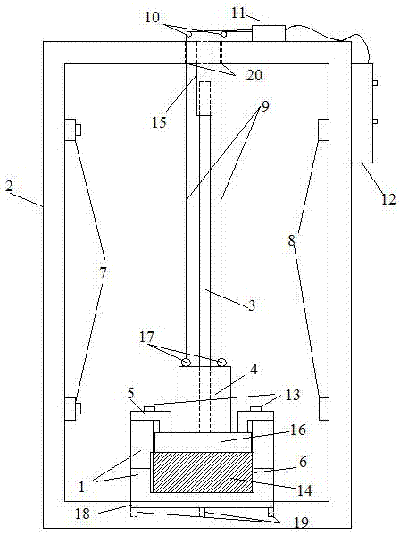
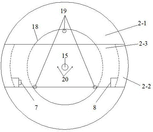
[0027] Such as Figure 1-2 A compacted soil sample test device shown includes a support 2, a compaction system, a sample preparation mold 1 and a control system, the support base 2-1 is a circular frame, and support side plates are provided on both sides of the support base 2-1 2-2, the support side plate 2-2 is an arc long plate, the upper top surface of the support 2 is provided with a support top plate 2-3, and the top of the support top plate 2-3 middle part is provided with a motor 11 and a pulley block 10, and 9 one ends of the traction rope are connected to the The motor 11 is connected, the other end bypasses the pulley block 10 and then passes through the traction hole 20 in the middle of the bracket top plate 2-3 to connect with the connection hole 17 above the hammer 4; the compaction system includes a guide rod 3, a hammer 4 , compaction base plate 16 and limit plate 5, guide rod 3 is located at the middle part of support top plate 2-3, guide rod 3 is provided with...
Embodiment 2
[0029] A compacted soil sample test device, the support base 2-1 is provided with a circular groove 18, the bottom of the groove 18 has a positioning hole 19, and the diameter of the circular groove 18 matches the diameter of the sample preparation mold 1; The bracket base 2-1 is a circular rigid base with a thickness of 15mm and a diameter of 12cm. The positioning groove is cylindrical and fixed in the rigid base. The depth of the groove is 5mm. There are 3 positioning holes inside the groove, and the diameter of the positioning hole is 5mm. , depth 5mm; rigid body thickness 10mm, width 50mm, height matches the height of the ring knife and the guide rod. The diameter of the positioning sleeve 15 is larger than that of the guide rod 3, the positioning sleeve 15 matches the guide rod 3, and the positioning sleeve 15 passes through the support top plate 2-3. Other structures are the same as in Embodiment 1.
Embodiment 3
[0031]A compacted soil sample test device, the limiting plate 5 is ┓ type, the limiting plate 5 is fixedly connected to the compacted bottom plate 16, and the difference between the height of the top surface of the compacted bottom plate 16 and the height of the bottom surface of the positioning sleeve 15 is less than the height of the guide The height of pole 3. , the guide rod is a solid steel column with a diameter of 10mm, the compacted bottom plate is a rigid steel plate with a diameter of 60.8mm and a height of 10mm, and the hammer is a rigid hollow cylinder with an inner diameter of 11mm and an outer diameter of 50mm and a height of 60mm. The limiting plate is a rigid steel plate with a thickness of 10mm, a width of 10mm, and a height of 30mm. The height of the limiting plate is equal to the difference between the 40mm upper cylinder of the upper part of the sample preparation mold and the 10mm thickness of the compacted bottom plate. The upper part of the hammer 4 is sy...
PUM
| Property | Measurement | Unit |
|---|---|---|
| height | aaaaa | aaaaa |
| diameter | aaaaa | aaaaa |
| thickness | aaaaa | aaaaa |
Abstract
Description
Claims
Application Information
 - R&D
- Intellectual Property
- Life Sciences
- Materials
- Tech Scout
- Unparalleled Data Quality
- Higher Quality Content
- 60% Fewer Hallucinations
Browse by: Latest US Patents, China's latest patents, Technical Efficacy Thesaurus, Application Domain, Technology Topic, Popular Technical Reports.
© 2025 PatSnap. All rights reserved.Legal|Privacy policy|Modern Slavery Act Transparency Statement|Sitemap|About US| Contact US: help@patsnap.com


