Loading device for calibrating displacement sensor, and calibration method

A displacement sensor and loading device technology, applied in the direction of using electrical devices, measuring devices, instruments, etc., can solve problems such as large errors, few measurement points, and inability to meet the calibration requirements of displacement sensors of different types and ranges, and achieve rapid data processing Intuitive, compact and reasonable effect of position setting

Active Publication Date: 2017-08-11
HANGZHOU JIPU TECH
View PDF5 Cites 7 Cited by
  • Summary
  • Abstract
  • Description
  • Claims
  • Application Information

AI Technical Summary

Problems solved by technology

[0003] During the use of the displacement sensor, the sensitivity coefficient will change with the prolongation of time and the aging of electronic components. If the calibration is not changed in time, it will lead to the measurement error The large data deviation will affect the measurement results
[0004]The existing displacement sensor calibration device has a single function and complicated operation, and cannot meet the calibration requirements of different types and ranges of displacement sensors
At present, most of the calibration methods of displacement sensors adopt manual static calibration. The displacement sensor is fixed on the calibration device, the sensor is manually moved in a straight line, and the signal value output by the sensor is measured with a multimeter, and the displacement value of the axial movement is recorded at the same time. One-to-one correspondence to obtain the calibration curve, this method has fewer measurement points for calibration, large error, and single function

Method used


Image

  • Loading device for calibrating displacement sensor, and calibration method
  • Loading device for calibrating displacement sensor, and calibration method
  • Loading device for calibrating displacement sensor, and calibration method

Examples


Embodiment 1

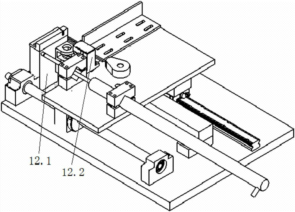
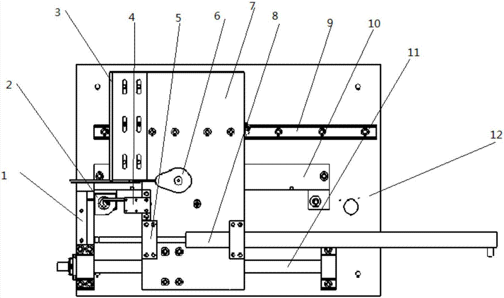
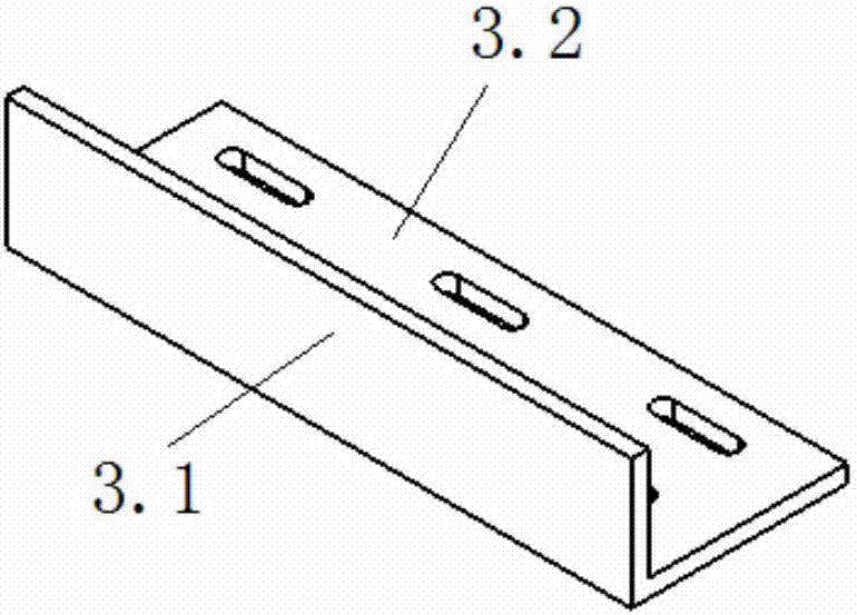
[0038] The loading device for calibration of the displacement sensor of the present invention is as figure 1 (Some details of which are not in the figure 1 Shown in , such as the mounting holes on the movable plate 7, etc., please refer to the detailed structure of the parts not shown figure 2 ) and 2, including a base plate 12, the loading device is fixed on the work table through the base plate 12, which reduces the accidental error caused by position offset during the calibration process. For convenience of description, the present invention uses figure 2 The left direction shown is the rear, and the right direction is the front (the front and rear direction is the moving direction of movable plate 7); image 3 The bottom of the page shown is left and the top of the page is shown right.

[0039] On the upper surface of the base 12, a ball screw 11, a grating ruler 10 and a linear guide 9 are arranged in parallel in sequence from left to right, and the three should be h...


PUM


Abstract

The invention discloses a loading device for calibrating a displacement sensor, and a calibration method. The loading device comprises a substrate, and the substrate is sequentially provided with a ball screw, a grating ruler and a linear guide rail in a parallel manner. A movable plate is disposed above the linear guide rail, the grating ruler and the ball screw. The movable plate is driven by the ball screw to move along the linear guide rail. The substrate or the movable plate is provided with fixing parts which are respectively used for fixing a stay wire sensor, an angular displacement sensor and a spring automatic telescoping displacement sensor, and enabling the stay wire sensor, the angular displacement sensor and the spring automatic telescoping displacement sensor to move with the movable plate to generate stay wire displacement, angular displacement and spring automatic telescoping displacement. The positions of the fixing parts of the three types of displacement sensors in the loading device are set compactly and reasonably. The device and method can complete the calibration of various types of displacement sensors with different ranges quickly and efficiently, and the disassembly of the sensors is convenient and simple. The data processing is quick and visual. The device is especially suitable for the calibration of a displacement sensor for an automobile impact test.

Description

technical field [0001] The invention relates to a loading device for calibrating a displacement sensor and a method for calibrating the displacement sensor by using the loading device, belonging to the field of calibrating sensors. Background technique [0002] Sensor calibration is the process of using standard instruments with higher precision to calibrate the sensor, so as to establish the corresponding relationship between the sensor output and input. At the same time, the error relationship under different conditions of use is also determined. The basic method of calibration is to use a standard instrument to generate a known non-electric quantity as an input quantity, input it into the sensor to be calibrated, and then compare the output quantity of the sensor with the input standard quantity to obtain a series of standard data or curves. Determining the performance indicators of the sensor based on the test data is actually determining the measurement accuracy of the...

Claims


Application Information

Patent Timeline
Patent Type & Authority Applications(China)
IPC IPC(8): G01B7/02G01B7/30
CPCG01B7/02G01B7/30Y02E30/30
Inventor 杨建
Owner HANGZHOU JIPU TECH
Why Eureka
Try Eureka