Tension control optimization method during welding tail swinging of cold-rolling strip steel

A technology for tension control and cold-rolled strip steel, applied in the direction of tension/pressure control, etc., can solve problems such as inability to optimize tension control

Inactive Publication Date: 2017-06-09
BAOSHAN IRON & STEEL CO LTD
View PDF6 Cites 8 Cited by
  • Summary
  • Abstract
  • Description
  • Claims
  • Application Information

AI Technical Summary

Problems solved by technology

[0015] Comparison results: This patent discloses a control method for reducing tailing of hot-rolled strip steel, which is mainly aimed at setting the starting frame and the subsequent frame at the same time with a preset lift for each frame. A comprehensive automatic control technology field of tail setting, but this technology cannot be applied to the optimization of tension control during strip welding tail flicking

Method used


Image

  • Tension control optimization method during welding tail swinging of cold-rolling strip steel
  • Tension control optimization method during welding tail swinging of cold-rolling strip steel
  • Tension control optimization method during welding tail swinging of cold-rolling strip steel

Examples


Embodiment Construction

[0033] The technical solutions of the present invention will be further described below in conjunction with the accompanying drawings and embodiments.

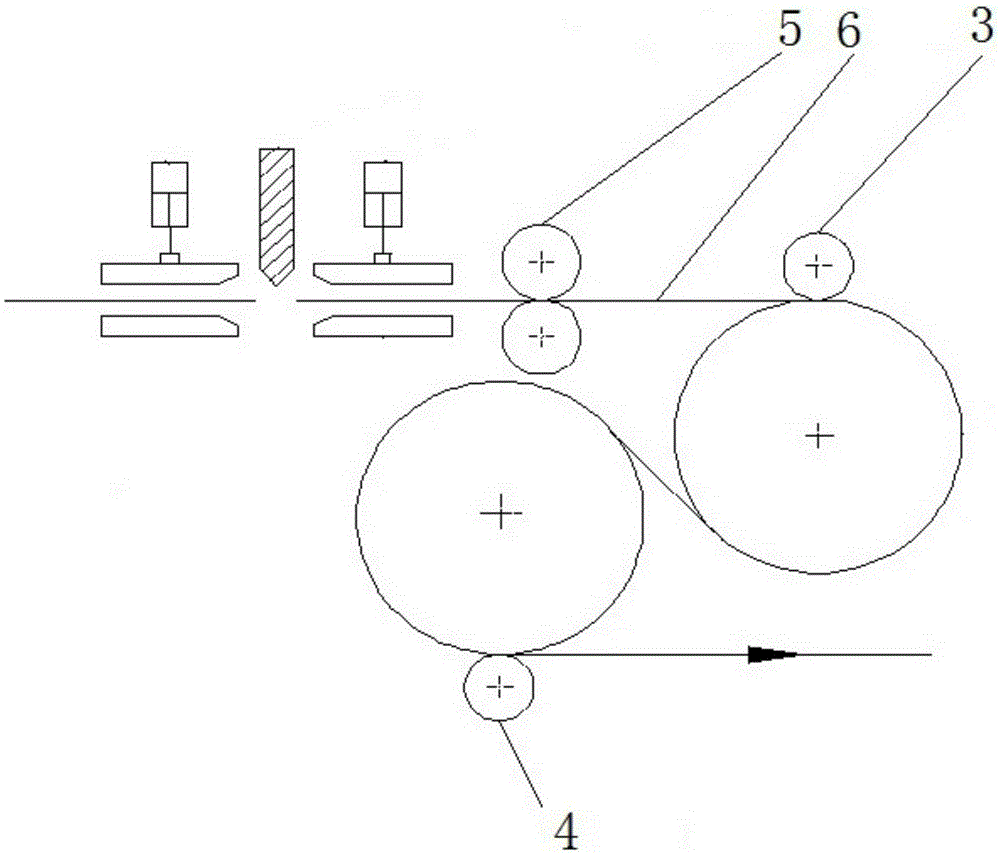
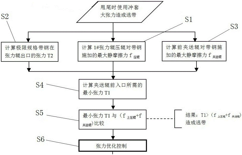
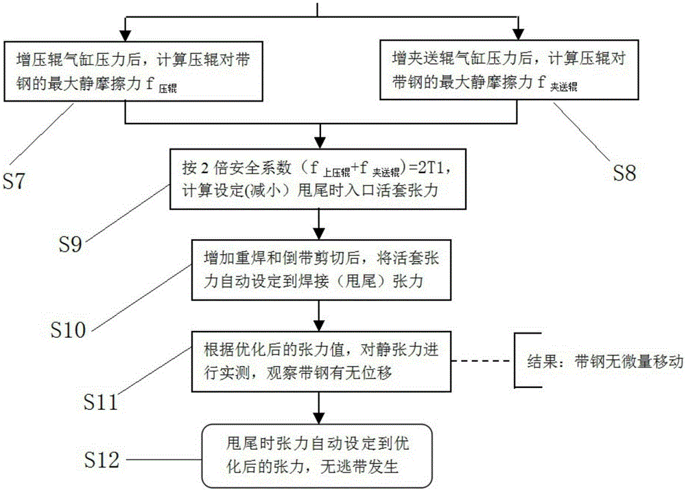
[0034] refer to Figure 2A and 2B , the present invention discloses a tension control optimization method for cold-rolled strip welding tailing. The problem to be solved is the strip escape problem caused by the high tension of the punching sleeve when the rolling mill is tailing. It can be mainly realized by the following steps.

[0035] First, calculate the maximum static friction force after the tension roller and the pinch roller 5 place the cylinder action of the pressure roller to exert pressure on the strip 6. This step can be subdivided into S1-S3.

[0036] S1: Calculate the maximum static friction force f exerted by the 1# tension roller on the strip 6 压辊 .

[0037] S2: Calculate the tension T2 of the strip steel 6 of the limit specification at the exit of the tension roller.

[0038] S3: The maximum static frict...


PUM


Abstract

The invention discloses a tension control optimization method during welding tail swinging of cold-rolling strip steel. The method includes the following steps that the required minimum tension of an inlet in front of pinch rolls is calculated; the minimum tension is compared with the total pressure of an upper pressuring roll and the pinch rolls; and optimization controlling is performed on tension. By means of the tension control optimization method during welding tail swinging of the cold-rolling strip steel, no abnormal deviation of the strip steel in a loop can be guaranteed, and the effects that no abnormal escape of a strip tail occurs and the welding quality is not affected are guaranteed.

Description

technical field [0001] The invention relates to a method for optimizing tension control, more specifically, to a method for optimizing tension control during cold-rolled strip welding flick. Background technique [0002] In order to ensure continuous production in a pickling production line, a 1# looper is installed at the pickling entrance, which is used to continuously transport the strip steel to the process section when the 1# looper is stopped for welding at the entrance section. When the pickling entrance stops, the tension of the 1# looper at the entrance is provided by the 1# tension roller in front of the looper and the 1# looper winch. When flicking to the welding machine, the static tension provided by the 1# tension roller when it stops (the upper and lower pressure rollers of the 1# tension roller and the pinch roller clamping the strip in front of the 1# tension roller) are limited. In the middle, due to the tension problem in the 1# looper at the entrance, th...

Claims


Application Information

Patent Timeline
Patent Type & Authority Applications(China)
IPC IPC(8): B21B37/50
CPCB21B37/50
Inventor 杨建林
Owner BAOSHAN IRON & STEEL CO LTD
Why Eureka
Try Eureka