Screen frame lifting device for printing machine

A technology for lifting devices and printing machines, applied to printing machines, rotary printing machines, screen printing machines, etc., can solve the problems of low motion precision and large space occupation, and achieve the effect of reducing space and ensuring precision and rigidity requirements

Inactive Publication Date: 2014-01-15
THE 45TH RES INST OF CETC
View PDF6 Cites 5 Cited by
  • Summary
  • Abstract
  • Description
  • Claims
  • Application Information

AI Technical Summary

Problems solved by technology

[0003] The purpose of the present invention is to provide a screen frame lifting device for a printing machine to solve the technical problems of large space occupation and low motion precision in the prior art

Method used


Image

  • Screen frame lifting device for printing machine
  • Screen frame lifting device for printing machine
  • Screen frame lifting device for printing machine

Examples


Embodiment Construction

[0024] The present invention will be further described in detail below in conjunction with the embodiments and the accompanying drawings, but the embodiments of the present invention are not limited thereto.

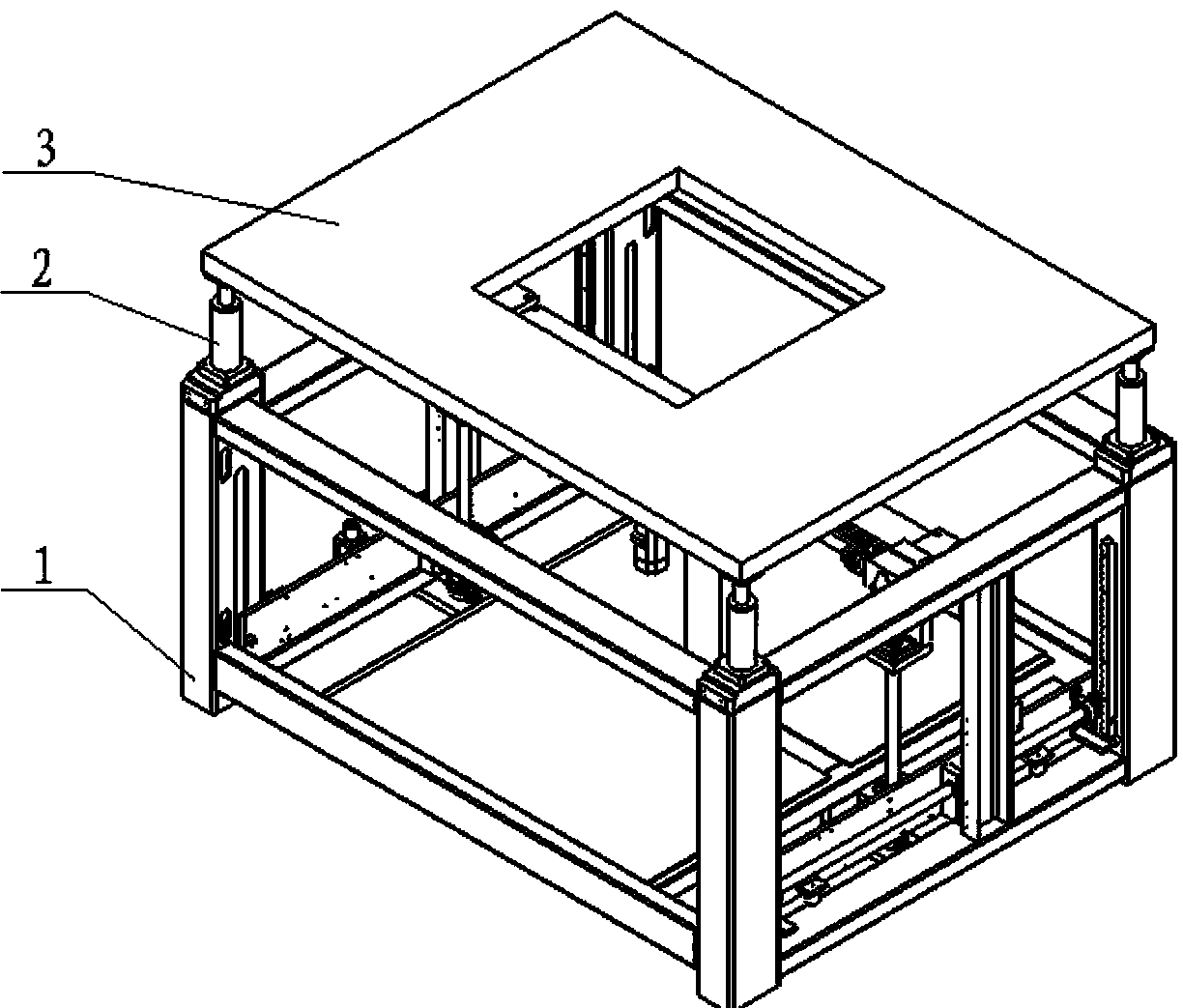
[0025] refer to figure 1 As shown, the present invention provides a screen frame lifting device for a printing machine, which includes a frame 1 , a lifting transmission device 2 mounted on the frame 1 , and a screen frame 3 mounted on the lifting transmission device 2 .

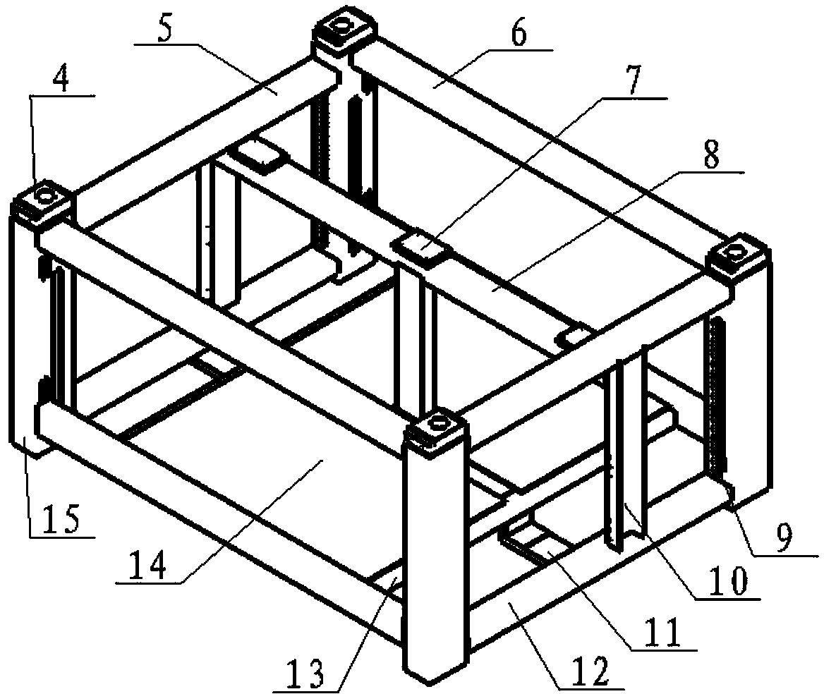
[0026] Among them, see figure 2 As shown, the frame 1 includes a frame body and bearing supports 4 arranged at four corners of the frame body. Specifically, the frame body includes four vertical beams 15 for installing the bearing support 4, four first short beams 5 and four first long beams 6 lapped on the upper and lower ends of the four vertical beams 15, installed The bottom plate 14 at the lower end of the vertical beam 15, the second long beam 8 installed between the first short beams 5 at the...


PUM


Abstract

The invention discloses a screen frame lifting device for a printing machine. The screen frame lifting device for the printing machine comprises a machine frame, a lifting transmission device and a screen frame, wherein the lifting transmission device is installed on the machine frame, and the screen frame is installed on the lifting transmission device. The screen frame can be widely applied to large-area self-aligning printing machines, the space of the whole device is greatly reduced, and meanwhile the demands for precision and rigidity of the screen frame in the process of lifting are met.

Description

technical field [0001] The invention relates to the technical field of printing machines, and more specifically relates to a screen frame lifting device for printing machines that occupies less space and has high motion precision. Background technique [0002] With the development of the packaging substrate and flat panel display industry, the size of the printed items needs to increase continuously, and the corresponding screen frame size also increases accordingly; take the printed item size of 600mm×600mm as an example: the screen frame size needs to be at least 1100mm×1100mm. The minimum size of the lifting device for fixing the screen frame needs to be 1500mm×1500mm; the traditional small-area printing machine places the screen frame lifting mechanism on the platen of the equipment, and uses a motor to drive the screen frame up and down synchronously; Due to the large footprint and low motion accuracy, it cannot be realized by traditional methods. Therefore, need to de...

Claims


Application Information

Patent Timeline
IPC IPC(8): B41F15/36
Inventor 张世强杨志王慧霞朱林涛
Owner THE 45TH RES INST OF CETC
Why Eureka
Try Eureka