
Uniform coloring machine of fibers

A uniform and optical fiber technology, applied in the field of optical fiber uniform coloring machine, can solve the problems of damaging the aesthetics and affecting the application of optical fibers, and achieve the effect of avoiding uneven dyeing and improving dyeing quality

Inactive Publication Date: 2014-01-15
成都亨通光通信有限公司
View PDF3 Cites 9 Cited by
  • Summary
  • Abstract
  • Description
  • Claims
  • Application Information

AI Technical Summary

Problems solved by technology

After the optical fiber is produced, it is generally necessary to dye the color, which is convenient to use. However, when the existing optical fiber coloring machine is dyeing, the fiber is often too loose, resulting in uniform dyeing, and even some places are not dyed, which not only destroys the aesthetics, but also Affected the application of optical fiber

Method used

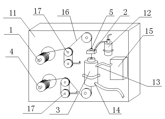

Image

  • Uniform coloring machine of fibers
  • Uniform coloring machine of fibers
  • Uniform coloring machine of fibers

Examples


Embodiment Construction

[0016] Below in conjunction with embodiment the present invention is described in further detail, but structure of the present invention is not limited to following embodiment:

[0017] 【Example】

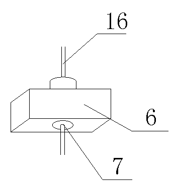
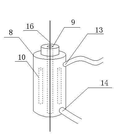
[0018] Such as Figure 1~4 As shown, the optical fiber uniform coloring machine includes a base 11 and a pay-off reel 1 installed on the base 11, a shader 2, a curing furnace 3, a take-up reel 4, and a color tank 12. The pay-off reel 1 , the shader 2, the curing furnace 3 and the take-up reel 4 are arranged in a ring, a tension regulator 17 is arranged between the pay-off reel 1 and the shader 2, and a tension regulator 17 is also arranged between the curing furnace 3 and the take-up reel 4 The tension regulator 17, the pay-off reel 1 and the take-up reel 4 are respectively installed on the support 11 through a motor.

[0019] Further, the above-mentioned tension regulator 17 includes a static turntable 18 and a moving turntable 19, the static turntable 18 is mounted on the machin...


PUM


Abstract

The invention discloses a uniform coloring machine of fibers. The machine comprises a base (11), and a pay-off reel (1), a coloring device (2), a curing furnace (3), a take-up reel (4) and a pigment pot (12) which are installed on the base (11), the pay-off reel (1), the coloring device (2), the curing furnace (3) and the take-up reel (4) are annularly assigned, a tension regulator (17) is arranged between the pay-off reel (1) and the coloring device (2), a tension regulator (17) is also arranged between the curing furnace (3) and the take-up reel (4), and the pay-off reel (1) and the take-up reel (4) are respectively installed on the base (11) through a motor. The machine which allows the tension regulator to be arranged in each of a pay-off position and a take-up position has the advantages of guarantee of the tension in fiber transmission, no fiber relax phenomenon, avoiding of the non-uniform dyeing phenomenon, and improvement of the fiber dying quality.

Description

technical field [0001] The invention relates to a dyeing device, especially a uniform dyeing machine designed to optical fiber. Background technique [0002] Optical fiber is the abbreviation of optical fiber, which is a light transmission tool achieved by the principle of total reflection of light in fibers made of glass or plastic. After the optical fiber is produced, it is generally necessary to dye the color, which is convenient to use. However, when the existing optical fiber coloring machine is dyeing, the fiber is often too loose, resulting in uniform dyeing, and even some places are not dyed, which not only destroys the aesthetics, but also It affects the application of optical fiber. Contents of the invention [0003] The purpose of the present invention is to overcome the deficiencies of the current technology and provide a uniform coloring machine for optical fiber with simple structure and simple operation. [0004] The present invention is achieved through t...

Claims


Application Information

Patent Timeline
Patent Type & Authority Applications(China)
IPC IPC(8): C03C25/16
Inventor 孙义兴何吉焱许建国陈曲刘东陈治均
Owner 成都亨通光通信有限公司
Learn More