Engine limit load control method and device

A technology of limit load and control method, applied in engine control, machine/engine, non-electrical control, etc., can solve problems such as engine flameout

Active Publication Date: 2014-01-15
ZOOMLION HEAVY IND CO LTD
View PDF4 Cites 2 Cited by
  • Summary
  • Abstract
  • Description
  • Claims
  • Application Information

AI Technical Summary

Problems solved by technology

[0004] The purpose of the present invention is to provide a method and device for controlling the limit load of the eng...

Method used


Image

  • Engine limit load control method and device
  • Engine limit load control method and device
  • Engine limit load control method and device

Examples


Embodiment Construction

[0020] Embodiments of the invention are described in detail below, but the invention can be practiced in many different ways as defined and covered by the claims.

[0021] As a first aspect of the present invention, an engine limit load control device is provided, in particular, it can be used to implement the engine limit load control method in the present invention.

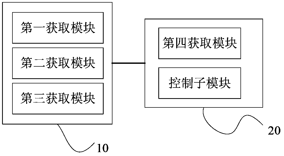
[0022] Please refer to figure 1 , the engine limit load control device includes: an acquisition module 10 and a control module 20 . Wherein, the obtaining module 10 is used for obtaining the maximum output torque of the engine in real time; the control module 20 is used for controlling the torque consumed by the hydraulic system driven by the engine to always be smaller than the maximum output torque.

[0023] At a certain moment, the engine of the engineering equipment has a first rotational speed, and has a maximum output torque corresponding to the first rotational speed, that is, when the engine is running...


PUM


Abstract

The invention provides an engine limit load control method and device. The engine limit load control method includes the steps of obtaining the current rotating speed of an engine, obtaining a rotating speed/torque relation graph of the engine, dividing the rotating speed/torque relation graph into multiple areas according to the rotating speeds, using a straight line section to connect a start point of each area with the end point of the area to obtain a rotating speed/torque relation curve of the engine, obtaining the largest output torque corresponding to the current rotating speed according to the rotating speed/torque relation curve, and controlling the torque consumed by a hydraulic system driven by the engine to be always smaller than the largest output torque. The largest output torque which can be supplied by the engine at some moment can be obtained in real time, meanwhile, the size of the torque consumed by the hydraulic system is controlled, and therefore the torque can be always smaller than the largest output torque which can be outputted by the engine, so that the engine can supply enough power for the hydraulic system, and the hydraulic system can not be shut down under various working conditions.

Description

technical field [0001] The present invention relates to the field of engine load control, and more particularly relates to a method and device for controlling engine limit load. Background technique [0002] Crane is a kind of construction machinery with high power and high frequency of use, which consumes a lot of energy. With the rising price of energy and the increasing calls for environmental protection in the world, it is imminent to improve its energy-saving performance and work efficiency. At the same time, under the situation of shortage of global supporting parts resources and increasing costs, it is imperative to achieve economic matching of crane systems and achieve a "win-win" between manufacturers and users. [0003] When the crane in the prior art selects the engine on board, it is necessary to make the power output of the engine at idle speed greater than the maximum value of the power required by the hydraulic system in each working condition of the lifting ...

Claims


Application Information

Patent Timeline
IPC IPC(8): F02D39/00
Inventor 孙家勇曹书苾周庆喜
Owner ZOOMLION HEAVY IND CO LTD
Why Eureka
Try Eureka