Roots pump with rotor cooling structure

A technology of rotor cooling and Roots pump, which is applied to rotary piston type/swing piston type pump components, components of pumping devices for elastic fluid, pump components, etc. Poor cooling effect and other problems, to achieve the effect of improving service life, speeding up flow rate and facilitating circulation

Active Publication Date: 2014-01-15
杭州新安江工业泵有限公司
View PDF6 Cites 3 Cited by
  • Summary
  • Abstract
  • Description
  • Claims
  • Application Information

AI Technical Summary

Problems solved by technology

[0007] The invention overcomes the disadvantages of poor cooling effect on the rotor of the existing Roots pump and short service life of the Roots pump, and provides a Roots pump with a rotor cooling structure, which has a cooling effect on the rotor of the Roots pump Good, Extended Roots Pump Life

Method used


Image

  • Roots pump with rotor cooling structure
  • Roots pump with rotor cooling structure
  • Roots pump with rotor cooling structure

Examples


Embodiment 1

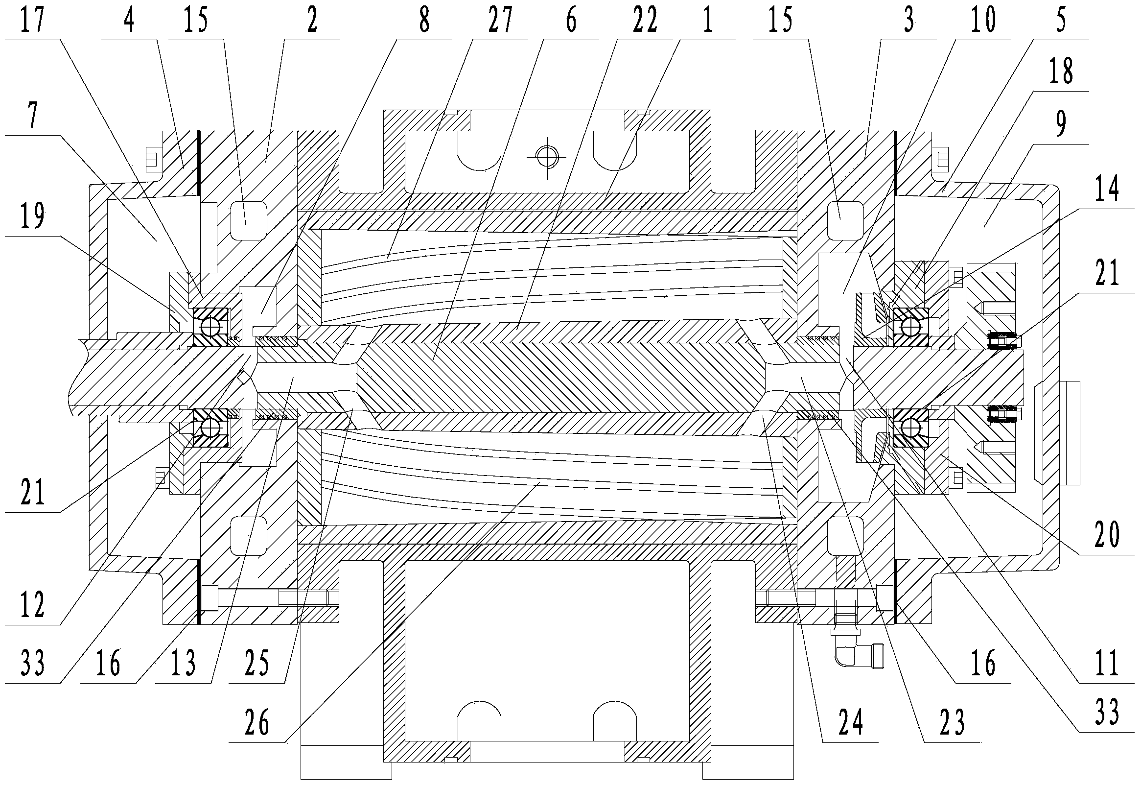
[0026] Embodiment 1: A Roots pump with rotor cooling structure (see attached figure 1 ), including the pump body 1, the front and rear ends of the pump body are respectively connected with the front side cover 2 and the rear side cover 3, the front side cover is connected with the front cover 4, the rear side cover is connected with the rear cover 5, the front cover and the front side cover The connecting position of the connecting position and the connecting position of the back cover and the rear side cover are all provided with a sealing gasket 16, a rotating shaft 6 is connected between the front cover and the back cover, and a rotor 22 is connected on the rotating shaft, and the rotor is arranged in the pump body. The front cover is provided with a front cover cavity 7, the front side cover is provided with a front cooling cavity 8, the rear cover is provided with a rear cover cavity 9, and the rear side cover is provided with a rear cooling cavity 10. A front bearing sea...

Embodiment 2

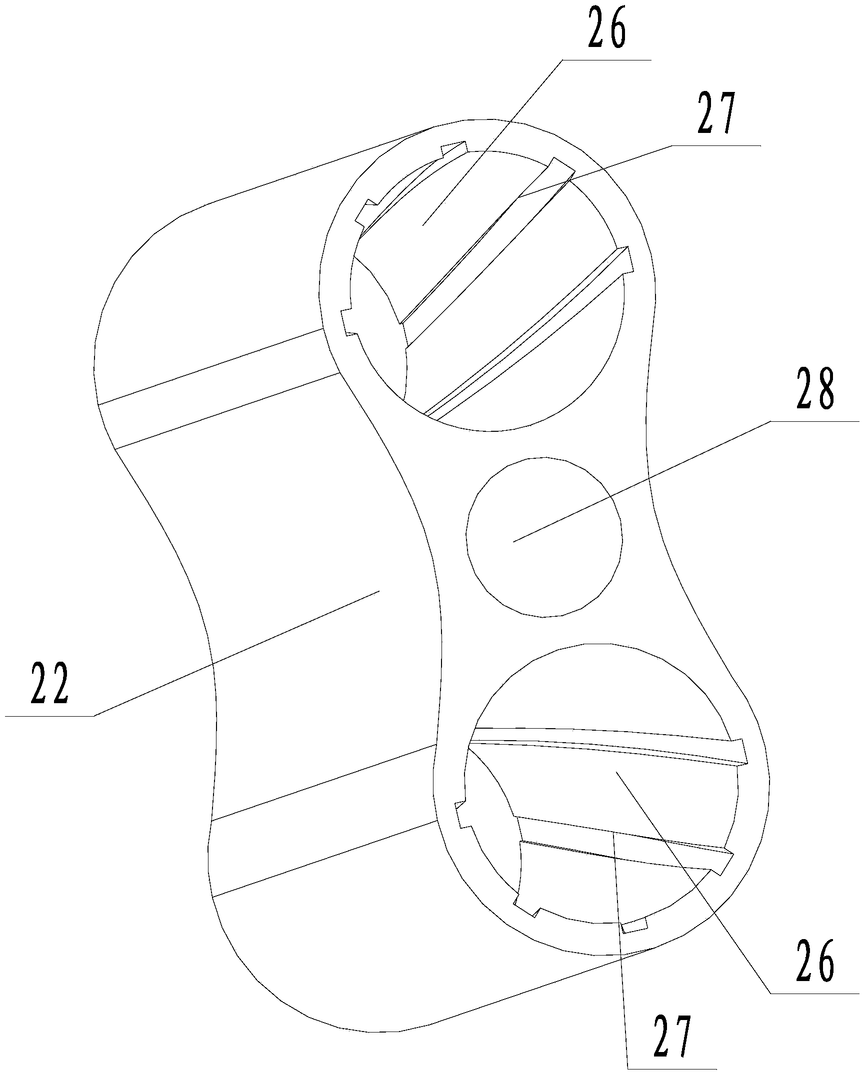
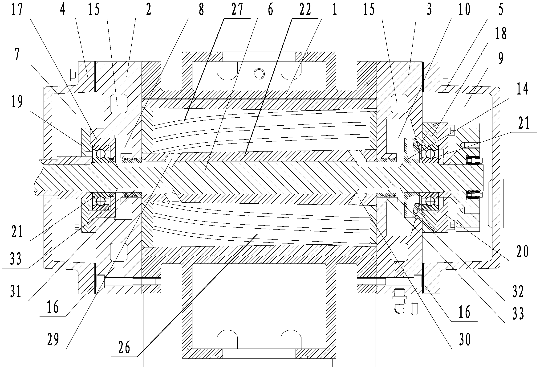
[0028] Embodiment 2: A Roots pump with rotor cooling structure (see attached image 3 ), its structure is similar to that of Embodiment 1, the main difference is that there is a connecting hole 28 in the middle of the rotor, the rotating shaft is fitted and connected in the connecting hole, and the inner walls of the connecting hole near the openings at both ends are respectively provided with two front connecting holes The hole 29 and the two rear communication holes 30, one front communication hole and one rear communication hole communicate with one rotor cooling chamber, and the other front communication hole and the other rear communication hole communicate with another rotor cooling chamber. Two front communication grooves 31 and two rear communication grooves 32 are respectively provided on the outer wall of the rotating shaft near the two ends of the rotor. Two back holes. The cooling water passes through the rear communication groove and the rear communication hole f...


PUM


Abstract

The invention discloses a roots pump with a rotating shaft cooling structure, and aims to overcome the defects of weaker rotating shaft cooling effect and short service life in the existing roots pump. The roots pump comprises a pump body, wherein the front end and the back end of the pump body are respectively connected with a front side cover and a back side cover; the front side cover is connected with a front cover; the back side cover is connected with a back cover; a rotating shaft is connected between the front cover and the back cover, and is connected with a rotor; a front cover cavity is formed in the front cover; a front cooling cavity is formed in the front side cover; a back cover cavity is formed in the back cover; a back cooling cavity is formed in the back side cover; the front cover cavity is communicated with the front cooling cavity; the back cover cavity is communicated with the back cooling cavity; the rotor takes the shape of 8, and is provided with two closed rotor cooling cavities inside; two ends of the rotor cooling cavities are respectively communicated with the front cooling cavity and the back cooling cavity; the rotor is provided with a centrifugal impeller for driving cooling liquid near to a liquid inlet hole; the centrifugal impeller is arranged in the back cooling cavity; a liquid inlet pipe is arranged on the back cover; a liquid outlet pipe is arranged on the front cover.

Description

[0001] technical field [0002] The present invention relates to a vacuum pump, more specifically, it relates to a Roots pump with good cooling effect and a rotor cooling structure. [0003] Background technique [0004] As a mechanical vacuum pump, the Roots pump has a wide range of applications. The service life of the Roots pump is not only affected by the use environment, but also the quality and performance of the Roots pump. One characteristic of the Roots pump is that it cannot work outside its required pressure difference range, because the higher the pressure difference, the more work the Roots pump will do and the more heat it will generate. Unreasonable and damaged. Therefore, the ability to withstand the pressure difference is an important indicator of the quality of the Roots pump. In this context, improving the cooling capacity of the pump becomes the key. The heat generated by the Roots pump during use mainly comes from the work done by the rotor. Ma...

Claims


Application Information

Patent Timeline
Patent Type & Authority Applications(China)
IPC IPC(8): F04C29/04
Inventor 李强
Owner 杭州新安江工业泵有限公司
Why Eureka
Try Eureka