Centrifugal pump

A centrifugal pump and impeller technology, applied in the field of centrifugal pumps, can solve the problems of high manufacturing and maintenance costs, inability to disassemble the back cover, short service life of the impeller, etc., and achieves improved service life, diversified fixing methods, and overall cost savings Effect

Inactive Publication Date: 2014-01-15
柳州市双铠工业技术有限公司
View PDF9 Cites 6 Cited by
  • Summary
  • Abstract
  • Description
  • Claims
  • Application Information

AI Technical Summary

Problems solved by technology

[0003] The purpose of the present invention is to provide a centrifugal pump, which can solve the problems in the prior art that the blades of the impeller cannot be separated fr

Method used


Image

  • Centrifugal pump
  • Centrifugal pump
  • Centrifugal pump

Examples


Example Embodiment

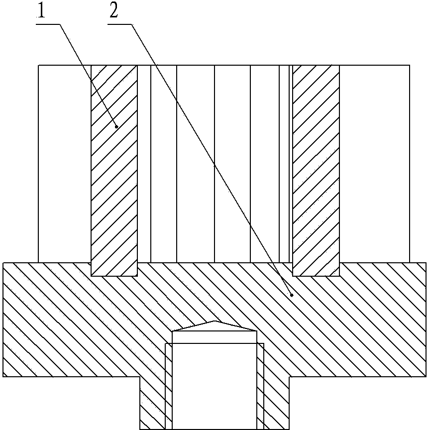
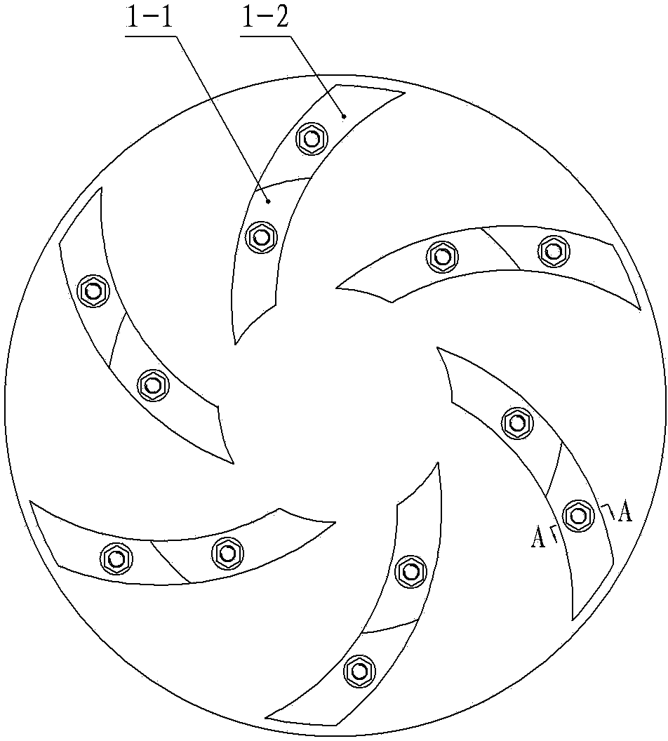
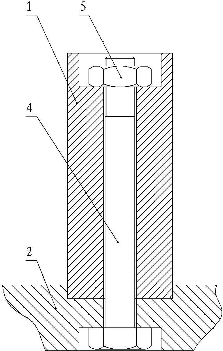
[0026] Example one: such as Figure 1~Figure 2 The centrifugal pump shown includes an impeller. The impeller includes a plurality of blades 1, and each blade is composed of at least two blade segments 1-1 and 1-2; the impeller also includes a rear cover plate 2, which is connected to the rear cover plate 2. The end face of the blade 1 is provided with a mounting slot for installing the blade 1; the bottom surface of the mounting slot is provided with a number of through holes, and the blade segments 1-1, 1-2 are provided with connecting through holes corresponding to the through holes of the mounting slot; The back of the plate 2 is provided with a countersunk screw hole coaxial with the through hole of the installation slot, and the back of the connecting end surface of the blade segment 1-1, 1-2 is provided with a connection hole coaxial with the blade segment 1-1, 1-2 Countersunk screw holes; the rear cover plate 2 is fastened to the blade segments 1-1, 1-2 by bolts 4 and nut...

Example Embodiment

[0029] Embodiment two: such as Figure 1~Figure 2 The centrifugal pump shown includes an impeller, the structure of the impeller is the same as that of the first embodiment; the rear cover 2 is made of a wear-resistant material with a hardness greater than or equal to HRC50, and the wear-resistant material is a ceramic material; the blade segments 1-1, 1-2 The blade segments 1-1 and 1-2 are inlaid with wear-resistant materials with hardness greater than or equal to HRC50, and the wear-resistant materials are ceramic materials.

Example Embodiment

[0030] Example three: such as Figure 1~Figure 2 The centrifugal pump shown includes an impeller, the structure of the impeller is the same as that of the first embodiment; the rear cover 2 is made of a wear-resistant material with a hardness greater than or equal to HRC50, and the wear-resistant material is a ceramic material; the blade segments 1-1, 1-2 The blade segments 1-1 and 1-2 are inlaid with wear-resistant materials with hardness greater than or equal to HRC50, and the wear-resistant materials are cemented carbide materials.


PUM


Abstract

The invention discloses a centrifugal pump, and relates to the technical field of radial flow pump manufacturing. The centrifugal pump comprises an impeller. The impeller is formed by blades and cover plates, and the blades are connected with the cover plates through connecting pieces. The centrifugal pump can solve the problems that the impeller is short in service life and high in manufacturing and maintenance cost due to the facts that the blades and the cover plates of the impeller cannot be split and the blades cannot be sectioned in the prior art.

Description

Technical field [0001] The invention relates to the technical field of centrifugal pump manufacturing, in particular to a centrifugal pump with a detachable impeller. Background technique [0002] At present, it is widely used in mining, metallurgy, electric power, chemical and other industries to produce centrifugal pumps (usually called slurry pumps or slurry pumps) for slag discharge, ore discharge, and sand excavation. Its impellers generally adopt two structural forms: open and closed. No matter which structure is adopted, the blades of the impeller and the front cover (or the rear cover) are made into one body during manufacturing; when the centrifugal pump transports solid and liquid mixed fluid, the centrifugal pump impeller works for a period of time. Its blades will be quickly worn out, which will affect the performance and service life of the centrifugal pump. In severe cases, it will damage the impeller and cause the centrifugal pump to stop. In order to improve the w...

Claims


Application Information

Patent Timeline
IPC IPC(8): F04D29/22F04D29/24F04D29/02
Inventor 韦成勋佘淑华
Owner 柳州市双铠工业技术有限公司
Why Eureka
Try Eureka