mechanical energy engine

An engine and mechanical energy technology, applied in the direction of machine/engine, variable displacement engine, reciprocating piston engine, etc., can solve the problem of engine energy consumption and workmanship, and achieve the effect of reasonable structure

Active Publication Date: 2018-05-15
喻名伟
View PDF12 Cites 0 Cited by
  • Summary
  • Abstract
  • Description
  • Claims
  • Application Information

AI Technical Summary

Problems solved by technology

[0002] At present, existing engines that can rotate the crankshaft, such as heat engines, gasoline engines, diesel engines, gas engines, etc., all use four-stroke combustion technology to make the piston do work, so that the connecting rod twists the crankshaft, but this existing four-stroke combustion technology Will cause the engine to consume energy

Method used


Image

  • mechanical energy engine
  • mechanical energy engine

Examples


Embodiment Construction

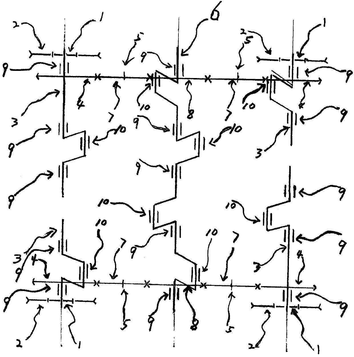
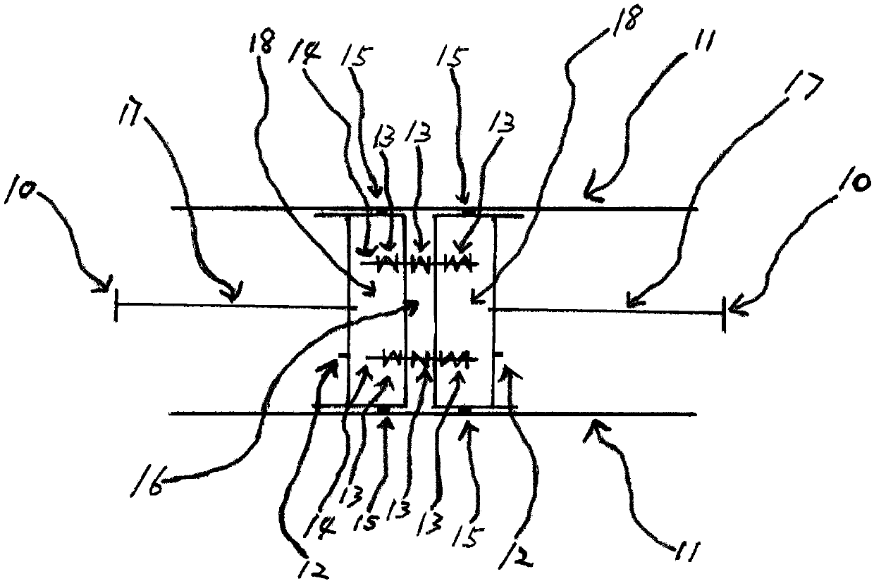
[0009] A mechanical energy engine such as figure 1 As shown, it includes oval cylinder 11, piston 18, piston shaft 12 and piston slip ring 15; also includes flywheel 1, pulley 2, journal seat 9, four secondary crankshafts 3, first synchronous gear 4, gear shaft 5 , second synchronous gear 8, main crankshaft 6, third synchronous gear 7, spring 13, connecting rod 14 and transmission rod 17; each auxiliary crankshaft 3 has a connecting pin 10, and four auxiliary crankshafts 3 are arranged in two matrixes row and two rows, the four auxiliary crankshafts 3 and the main crankshaft 6 are respectively limited by the fixed journal seats 9 and the respective main journals of the four auxiliary crankshafts 3 and the main crankshaft 6 are respectively connected to the corresponding journals in a manner of autorotation. The seats 9 are in motion fit, and the flywheel 1, the pulley 2 and the first synchronous gear 4 are fixed on the respective main journals of the four auxiliary crankshaft...


PUM


Abstract

A mechanical energy engine. A piston sliding ring (15) fits an inner-circumferential wall surface of a cylindrical channel in a dynamic seal manner. Two pistons (18) are connected to each other through a pair of connecting rods, two ends of the rod body of either connecting rod (14) pass into the body of a corresponding piston (18) through a rear-side end surface of the piston, respectively, so as to leave a gap between the two pistons (18). A middle rod body, located between two pistons, of either connecting rod (14) is fixedly mounted with a spring (13) disposed outside the piston (18), and both end rod bodies, that pass inside the corresponding piston (18), of the connecting rod (14) are also fixedly mounted with a spring (13) disposed inside the corresponding piston. When a belt pulley (2) is driven by an external force to rotate to drive rotation of four secondary crankshafts and drive rotation of a primary crankshaft (6) through three synchronous gears (4, 7, 8), the planes where crankpins (10) of two secondary crankshafts in each row are located are correspondingly parallel to a plane where a crankpin (10) of the primary crankshaft (6) is located, respectively.

Description

technical field [0001] The present invention relates to power plants, in particular mechanical energy engines. Background technique [0002] At present, existing engines that can rotate the crankshaft, such as heat engines, gasoline engines, diesel engines, gas engines, etc., all use four-stroke combustion technology to make the piston do work, so that the connecting rod twists the crankshaft, but this existing four-stroke combustion technology Will cause the engine to consume energy to work. Contents of the invention [0003] The object of the present invention is to provide a mechanical energy engine, which has a reasonable and simple structure, can output more mechanical energy, and can perform work with low energy consumption. [0004] The object of the present invention is achieved like this: a kind of mechanical energy motor, comprises cylinder block, piston, piston shaft and piston slip ring; Second synchronous gear, main crankshaft, third synchronous gear, spring...

Claims


Application Information

Patent Timeline
Patent Type & Authority Patents(China)
IPC IPC(8): F16H49/00
CPCF16H49/00F01B7/00
Inventor 喻名伟喻名可
Owner 喻名伟
Why Eureka
Try Eureka