Supercharge Your Innovation With Domain-Expert AI Agents!

Planetary gear mechanism

A technology of planetary gear transmission and planetary gear, which is applied in the direction of gear transmission, transmission, transmission parts, etc., and can solve problems such as high cost

Inactive Publication Date: 2014-01-15
ZF FRIEDRICHSHAFEN AG
View PDF10 Cites 6 Cited by
  • Summary
  • Abstract
  • Description
  • Claims
  • Application Information

AI Technical Summary

Problems solved by technology

The disadvantage of this known solution is that the bearing clearance of the tapered roller bearing can only be adjusted very cost-effectively by cutting or grinding methods

Method used


Image

  • Planetary gear mechanism
  • Planetary gear mechanism
  • Planetary gear mechanism

Examples


Embodiment Construction

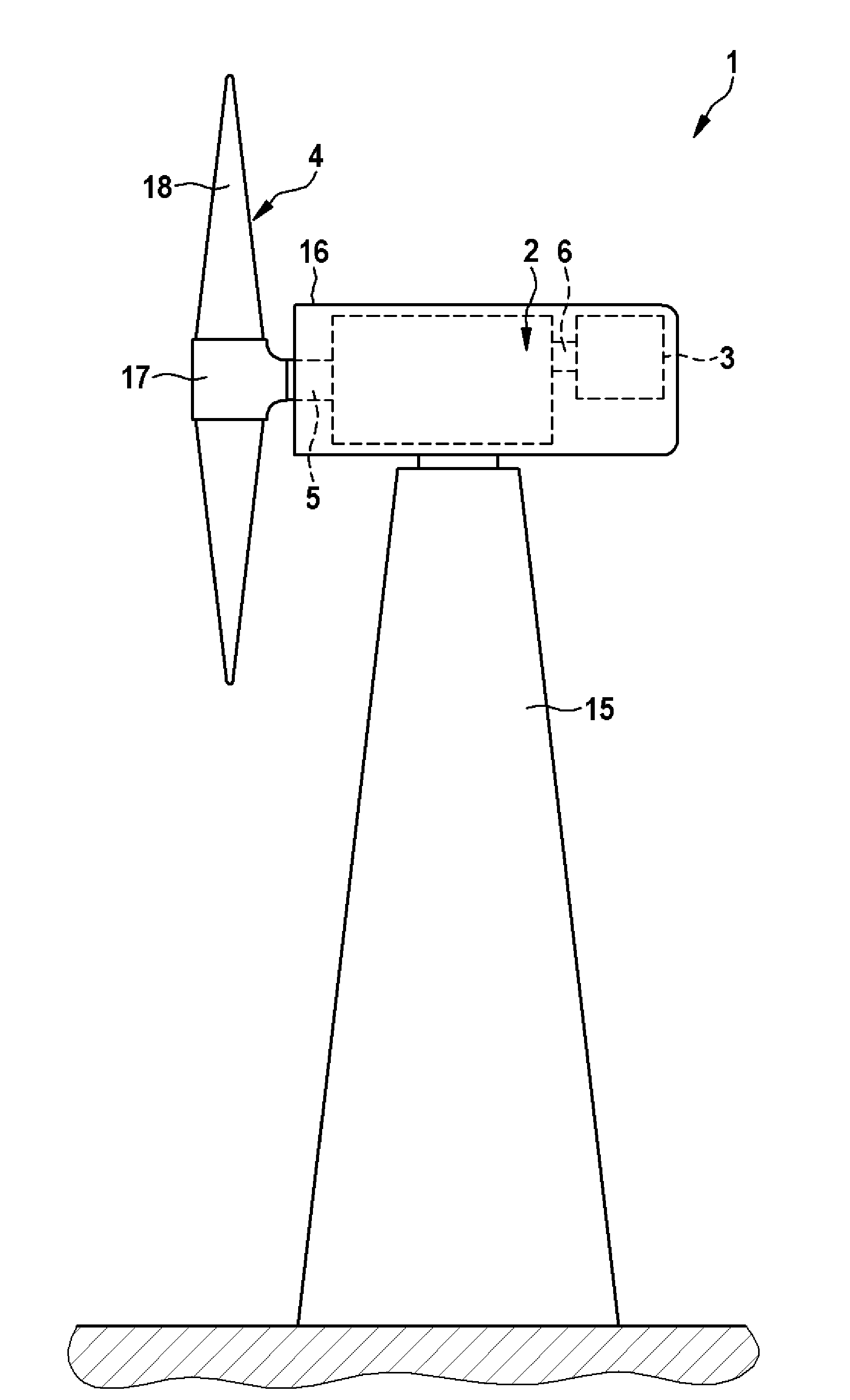
[0021] figure 1 A side view of the wind power plant 1 with its basic components is shown. The wind power plant 1 has a tower 15 on which a nacelle 16 in the form of a machine housing is arranged so as to be rotatable about a vertical axis. A planetary gear 2 is fastened in the gondola 16 in a rotationally fixed manner, wherein the planetary gear 2 has a drive shaft 5 and an output shaft 6 . Drive shaft 5 of planetary gear 2 is connected to hub 17 of rotor 4 with a plurality of rotor blades 18 . The driven shaft 6 is connected in rotation to a drive to be driven in the form of a generator 3 .

[0022] The planetary gear 2 is designed such that it converts a slow rotation of the drive shaft 5 into a fast rotation of the output shaft 6 . To this end, the planetary gear 2 has one or more planetary gear stages, which interact with the output shaft 6 via a closed spur gear. Electric energy is generated by means of a wind power plant 1 by introducing the rotation, which is trans...


PUM


Abstract

A planetary gear mechanism converts rotational movement of a drive shaft into rotational movement of an output shaft. The mechanism includes a planetary gear carrier for rotatably supporting a planetary gear, a planetary gear, and a bearing arrangement. The bearing arrangement includes roller bearings spaced apart between the planetary gear and planetary gear carrier. Each roller bearing has an inner ring and outer ring. The bearing arrangement includes a ring to position the roller bearings on the planetary gear carrier and a collar to secure the planetary gear. The ring is on an outer face of the planetary gear carrier between the inner rings. The collar is on an inner face of the planetary gear between the outer rings to axially position the planetary gear. At least one intermediate ring on the inner face of the planetary gear axially positions the roller bearings. The intermediate ring has a cutout directed to the collar which corresponds to an axial length of the collar.

Description

technical field [0001] The invention relates to a planetary gear for converting a slow rotation of a drive shaft into a fast rotation of a driven shaft, wherein the planetary gear has bearings on a planet carrier for rotatably mounting planet gears mechanism, the bearing mechanism includes at least two tapered roller bearings arranged axially apart from each other between the planetary gear and the planetary gear carrier, wherein the at least two tapered roller bearings each have an inner ring and an outer ring, and a washer is arranged between the two inner rings on the outer peripheral surface of the planetary gear carrier, and the washer is used to axially locate the at least two tapered roller bearings in the On the planet gear carrier, wherein a flange is also formed on the inner peripheral surface of the planet gear radially along the inner circumference of the planet gear between the two outer rings, the flange is used for The planetary gears are fixed axially. [000...

Claims


Application Information

Patent Timeline
IPC IPC(8): F16H57/08F03D11/04F16C19/54F16C19/22
CPCF16C19/542F16H57/08F16H2057/085Y02E10/72F05B2260/40311F16C35/067F16C19/543F16C2361/61F03D15/00F16C19/364F16C2360/31F03D15/10F03D80/70F16H1/2809
Inventor D.魏斯特
Owner ZF FRIEDRICHSHAFEN AG
Features
  • R&D
  • Intellectual Property
  • Life Sciences
  • Materials
  • Tech Scout
  • Unparalleled Data Quality
  • Higher Quality Content
  • 60% Fewer Hallucinations
Learn More