Supercharge Your Innovation With Domain-Expert AI Agents!

Sucker type solar lamp

A solar energy and suction cup technology, applied in the field of lighting, can solve the problem of fixing in one place and achieve the effect of convenient charging

Inactive Publication Date: 2014-01-15
SUZHOU CUIZHI NEW TECH DEV
View PDF0 Cites 1 Cited by
  • Summary
  • Abstract
  • Description
  • Claims
  • Application Information

AI Technical Summary

Problems solved by technology

However, the fixing methods of solar lamps in the prior art are all certain, and can only be fixed in one place or be portable.

Method used


Image

  • Sucker type solar lamp

Examples


Embodiment Construction

[0011] The present invention will be further described below in conjunction with the accompanying drawings and embodiments.

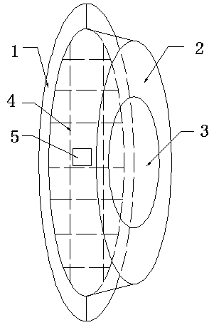
[0012] figure 1 It is a structural schematic diagram of the present invention, including a suction cup 1, a lamp housing 2, an LED lamp 3, a solar panel 4 and a switch button 5. The solar panel 4 and the recess of the suction cup 1 are combined and installed on one end of the lamp housing 2. A controller and a storage battery are arranged inside the lamp housing 2 , an LED lamp 3 is installed at the other end of the lamp housing 2 , and a switch button is also installed on the lamp housing 2 .

[0013] The suction cup 1 is preferably a transparent suction cup, which can maximize the light transmittance, so that the solar panel 4 can absorb enough sunlight. The solar cell panel 4 is preferably a thin-film solar cell panel, which can reduce volume and is convenient to carry.

[0014] The embodiment shown in this figure is a cylindrical lamp housing, and...


PUM


Abstract

The invention discloses a sucker type solar lamp which comprises a solar cell panel, a lamp shell, an LED lamp body, a switch button, a controller, a storage battery and a sucker, wherein the controller and the storage battery are installed in the lamp shell. The solar cell panel and a concave portion of the sucker are combined together and installed at one end of the lamp shell. The LED lamp body is installed at the other end of the lamp shell. The switch button is installed on the lamp shell. The sucker type solar lamp can be attached to glass of an office or a windscreen of a car in a sucking mode to be charged conveniently, and can also be fixed freely to be used as a decorative lamp.

Description

technical field [0001] The invention relates to the technical field of lighting, in particular to a suction cup type solar lamp. Background technique [0002] With the widespread application of solar energy, there are various kinds of solar lights now. But the fixing mode of the solar lamp in the prior art is all certain, can only be fixed in one place or be portable. The suction cup hook is a very common pendant, which can be adsorbed on the car glass or window glass, and it is very convenient to fix. Contents of the invention [0003] In order to solve the above technical problems, the present invention provides a suction cup type solar lamp, which can be charged on glass. [0004] The technical solution adopted in the present invention is: a sucker-type solar lamp, including a solar battery panel, a lamp housing, an LED lamp, a switch button, a controller and a battery installed in the lamp housing, and a sucker, the solar battery The combination of the plate and the...

Claims


Application Information

Patent Timeline
Patent Type & Authority Applications(China)
IPC IPC(8): F21L4/08F21V21/092F21Y101/02F21Y115/10
Inventor 孟繁茂
Owner SUZHOU CUIZHI NEW TECH DEV
Features
  • R&D
  • Intellectual Property
  • Life Sciences
  • Materials
  • Tech Scout
  • Unparalleled Data Quality
  • Higher Quality Content
  • 60% Fewer Hallucinations
Learn More