Zero-optical path difference interfering optical element

A technology of zero optical path difference and optical devices, which is applied in optical radiation measurement, scientific instruments, and measuring the polarization of light, etc., can solve the problem of not being able to obtain multiple polarization components and total light intensity at the same time, image registration errors cannot be eliminated, and evaluation Difficulties and other problems, to achieve the effect of simple structure, clear interference fringes, and no vibration

Active Publication Date: 2014-01-15
HEFEI UNIV OF TECH
View PDF5 Cites 1 Cited by
  • Summary
  • Abstract
  • Description
  • Claims
  • Application Information

AI Technical Summary

Problems solved by technology

The disadvantage of this measurement method is that it cannot obtain multiple polarization components and total light intensity of a scene at the same time, and when it is applied to a fast-moving platform or a rapidly changing scene, three-quarters of the information of the measured scene will be lost, and each image’s The registration error cannot be eliminated, and the evaluation is difficult

Method used


Image

  • Zero-optical path difference interfering optical element
  • Zero-optical path difference interfering optical element
  • Zero-optical path difference interfering optical element

Examples


Embodiment Construction

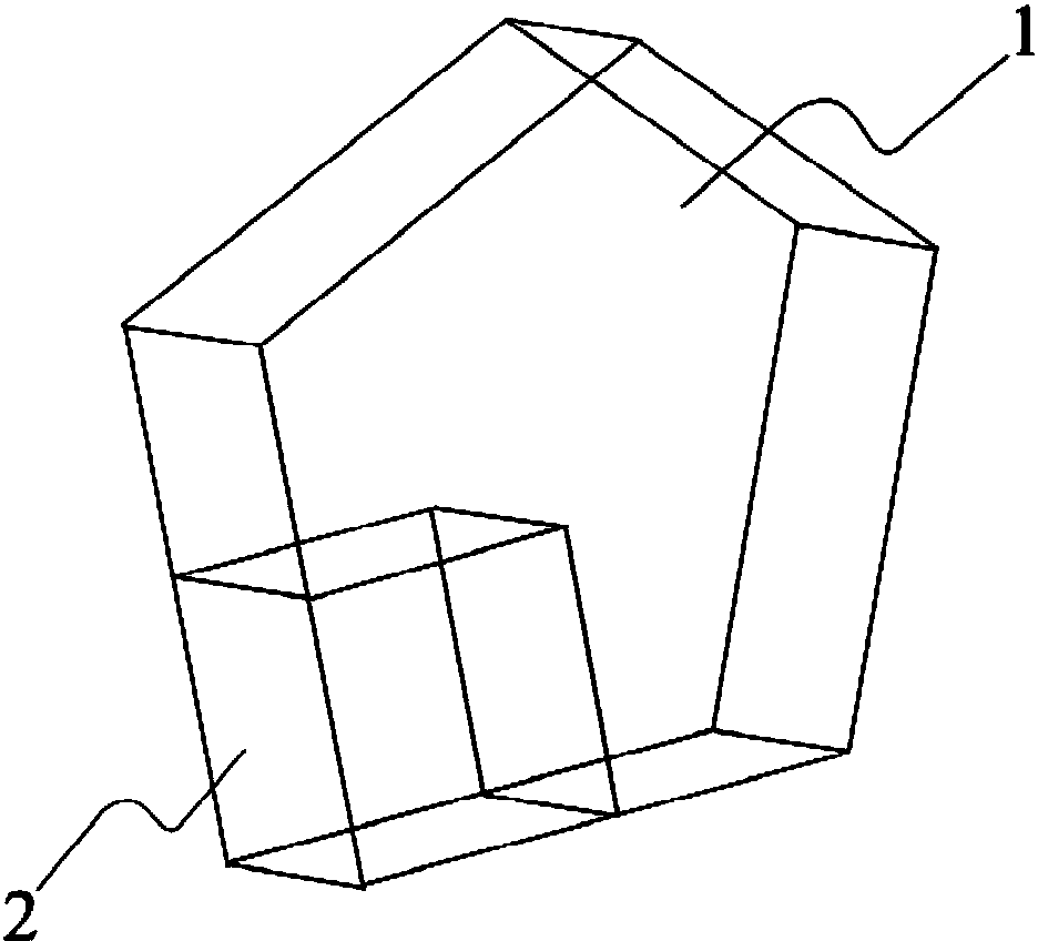
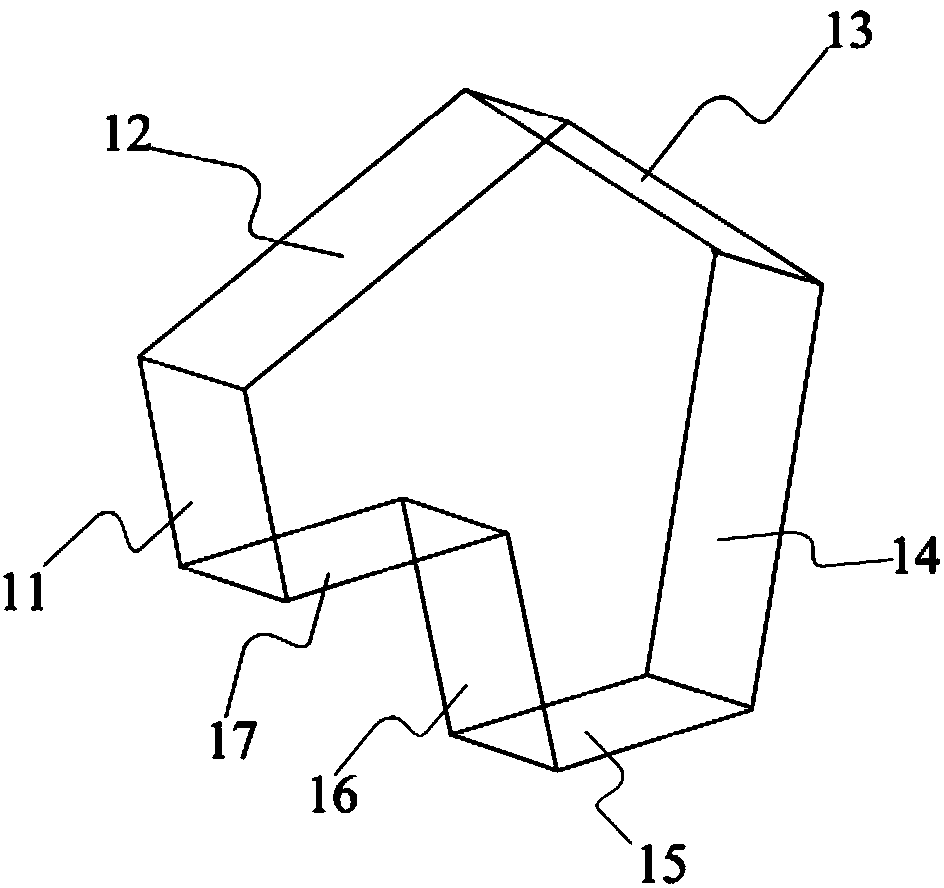
[0025] see figure 1 , the zero optical path difference interference optical device is a pentagonal pentagonal prism in the present embodiment, the lower left corner in the pentagon is a right-angled corner, and other corners are 112.5 °; in the pentagon, with An adjacent side of a right-angled edge is the first side, and the sides in the clockwise direction from the first side are the second side, the third side, the fourth side and the fifth side; the length ratio of each side is: The first side: the second side: the third side: the fourth side: the fifth side is 4:4:3:4:4, and the thickness of the pentaprism is half of the length of the first side;

[0026] The pentaprism is divided as follows:

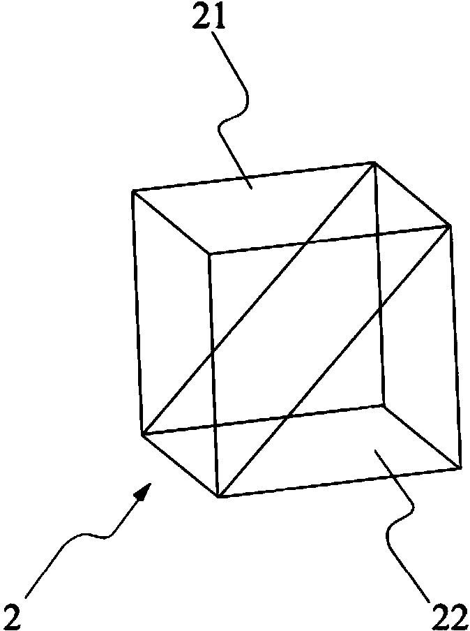
[0027] Such as image 3 As shown, take the right-angled corner in the pentaprism as the lower left corner, take the thickness of the pentaprism as the side length, divide a cube as the optical path deflection unit 2, and the remaining part constitutes the optical path reflection u...


PUM


Abstract

The invention discloses a zero-optical path difference interfering optical element. The zero-optical path difference interfering optical element is characterized in that a pentaprism is divided in a set way into a light path reflecting unit on the right upper part and a light path deflecting unit embedded on the left lower part of the reflecting unit respectively; the reflecting unit and the deflecting unit are repositioned according to corresponding positions before division and adhered to restore the shape of the pentaprism. The zero-optical path difference interfering optical element can achieve multi-spectral synchronous dispersion-free interference.

Description

technical field [0001] The invention relates to a zero optical path difference interference optical element. Background technique [0002] An interferometer is an instrument made according to the principle of light interference. A beam of light is divided into two beams, each of which passes through a different optical path, and then merged, and interference fringes can be obtained at the place where the light is merged. In the optical path, reflection, refraction, and diffraction are mostly used to realize the separation, deflection, and convergence of light. [0003] If the source beam is polychromatic light, the beam will produce dispersion in the optical path, causing the separated beams to diverge, making the interference fringes blurred or even unable to form interference, so the requirements for the wavelength range of light are relatively high. Generally, interferometers are only suitable for monochromatic light. Light. [0004] At present, there is only one princ...

Claims


Application Information

Patent Timeline
Patent Type & Authority Applications(China)
IPC IPC(8): G01J4/00G02B5/04
Inventor 金施群邢金玉张浩鹏李会玲
Owner HEFEI UNIV OF TECH
Why Eureka
Try Eureka